Strut Aluminium Profile 45×60 mm 4-Slot Column T-Slot Extrusion
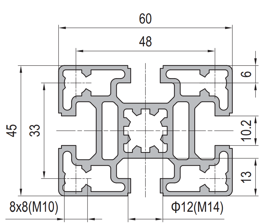
45 x 60 mm four-slot rectangular T-slot strut aluminium profile in 6063-T5, about 3.3 kg/m, used as a column. Four 8 x 8 mm slots on a 33 mm pitch, M10 slot nuts and a O 12 mm centre bore tapped M14 for end-wise bolting to base and top plates.
| Material | Aluminium |
|---|---|
| Alloy Grade | 6063-T5 |
| Temper | T5 |
| Section Size | 45 x 60 mm |
| Slot | 8 x 8 mm groove, M10 slot nuts, 4 faces, 33 mm pitch |
| Length | 6 m stock, cut to drawing to plus or minus 0.5 mm |
| Tolerance | EN 755-9 / GB/T 6892, wall plus or minus 0.15 mm |
| Surface | Mill finish / clear anodised / black anodised |
| MOQ | 400 |
| Lead Time | 22-32 days after deposit for mill finish |
| Loading Port | Qingdao / Shanghai |
| Supply Ability | 350 t per month |
| Payment Terms | T/T 30% deposit + 70% before shipment | L/C at sight |
| Trade Terms | FOB | CIF | EXW |
| Certifications | ISO 9001:2015 | EN 755-9 | RoHS | REACH |
Column section · 45 series
A 45 x 60 four-slot strut profile is a rectangular T-slot aluminium extrusion measuring 45 mm by 60 mm, with four 8 x 8 mm slots on a 33 mm pitch, M10 slot nuts, a O 12 mm centre bore tapped M14, and a weight of about 3.3 kg/m. It is a column section rather than a beam section: its job is to carry a vertical load and hold a frame square, not to span a gap.
The number that governs a column is not its compression area, it is its buckling load. At about 12.2 cm2 of aluminium the section would squash at roughly 200 kN, but a 2 m column with pinned ends buckles at about 54 kN about the 60 mm axis and only about 36 kN about the 45 mm axis. Buckling therefore governs by a factor of more than five, and the weak 45 mm direction is the one that decides the design. A 45 x 60 column is only as strong as the bracing that stops it bending in its narrow direction.
A tall narrow section is a column, not a beam
The instinct with any rectangular section is to lay it on edge and treat it as a beam. That is the right instinct for a 40 x 60 cross member and the wrong one for a 45 x 60 column. A column fails in a different way: it is pushed along its own length, and the failure mode is sideways buckling rather than bending between supports.
The consequence is that the two dimensions of a 45 x 60 are not interchangeable in a column. The 60 mm dimension gives about 31 cm4 and the 45 mm dimension about 21 cm4. A column braced in one plane only will always buckle in the other, and on this section that is the 45 mm plane. Sizing the column from the strong axis and forgetting the weak one is the single most common error on this member.
| Property | 45 x 45 standard | 45 x 60, weak axis | 45 x 60, strong axis |
|---|---|---|---|
| Envelope | 45 x 45 mm | 45 x 60 mm | 45 x 60 mm |
| Second moment of area | approx. 15.5 cm4 | approx. 21 cm4 | approx. 31 cm4 |
| Weight | approx. 2.55 kg/m | approx. 3.3 kg/m | approx. 3.3 kg/m |
| Euler buckling load, 2 m pinned | approx. 27 kN | approx. 36 kN | approx. 54 kN |
| Compression area | approx. 9.4 cm2 | approx. 12.2 cm2 | approx. 12.2 cm2 |
| Squash load, 6063-T5 | approx. 160 kN | approx. 200 kN | approx. 200 kN |
Buckling, not crushing, sizes the column. At 2 m the section buckles at roughly a quarter of the load that would crush it. Working loads must be taken from the buckling figure and a factor applied on top, never from the squash load. The numbers here are elastic Euler values for a pinned column and are meant for comparison, not as a design certificate.
Compression plus bending in two directions
Most real columns do not carry pure compression. A guard rail, a conveyor thrust, a cantilever arm or an unbalanced load puts a horizontal force into the column, and that force bends it. The design check is then an interaction: the axial load uses part of the capacity and the bending moment uses the rest, and the two are added as ratios.
On a 45 x 60 the interaction is asymmetric in a way that is easy to miss. A horizontal force along the 60 mm direction bends the column about its strong axis and is cheap to resist. The same force along the 45 mm direction bends it about the weak axis and costs roughly 50 per cent more stress for the same load. That is the mechanical reason the column has to be oriented deliberately rather than dropped into the layout.
- Axial load: taken on about 12.2 cm2 of aluminium, checked against buckling rather than squash
- Bending about the strong axis: about 31 cm4, the direction to arrange horizontal loads into where the layout allows
- Bending about the weak axis: about 21 cm4, and the direction that decides most columns
- Bracing: a mid-height beam, a diagonal or a panel is worth more to a 45 x 60 column than any increase in wall thickness
Which face goes where
A 45 x 60 has two 60 mm faces and two 45 mm faces, and each face carries one slot on the 33 mm pitch. Which face points outwards is a design decision with three consequences: what can be mounted on it, which way the bolts go in, and which axis the frame’s horizontal loads bend.
Mixing a 45 x 60 column with 45 x 45 beams
- Decide the column orientation before the layout Mark the 60 mm faces on the drawing as the faces that take the horizontal loads. Every later decision, panel position, bracket type and bolt direction, follows from that choice, and reversing it after the cut list is written means new drawings.
- Set the frame out on the 33 mm module The column and the beam share the 33 mm slot pitch and the M10 slot class, so M10 slot nuts and angle brackets work on both. Keep the frame grid on the 33 mm module and the beam slots will line up with the column slots without a single drilled hole.
- Detail the beam-to-column joint to the column face A 45 x 45 beam against a 45 mm column face needs no plate overhang, which is why the narrow face is the natural one for beams. Against a 60 mm face the beam leaves a 15 mm strip of column showing on one side, which is acceptable but should be intended.
- Brace the weak axis with the beams themselves A horizontal beam bolted to the 45 mm face at mid-height shortens the column’s buckling length in the weak direction. Where a frame has a mid rail, it is already doing structural work; where it does not, the column is 45 x 60 for nothing.
- Keep the foot detail separate from the column slot Columns carry compression and bending into the floor, so the foot is usually a base plate bolted through the end bore rather than a slot-mounted foot. Slot-mounted feet are for frames that only have to sit flat.
Frequently asked questions
Can I use 45 x 60 as a beam instead of a column?
You can, and on edge it gives about 31 cm4, which is respectable. But if the member spans rather than carries, a 45 x 60 laid as a beam should be compared against a deeper section first, because depth buys stiffness far more cheaply than width.
What load can a 45 x 60 column carry?
At 2 m with pinned ends the elastic buckling load is about 54 kN about the 60 mm axis and about 36 kN about the 45 mm axis. Design loads must come from the weak axis figure with a factor applied. Send the height and the bracing arrangement and we will confirm.
Why is the weak axis so important?
Because a column fails by buckling sideways, not by crushing. The 45 mm direction is about 50 per cent less stiff than the 60 mm direction, so it always governs unless it is braced. A mid-height beam or a panel usually fixes it at no extra material cost.
Do 45 x 60 and 45 x 45 share accessories?
Yes. Both sit on the 33 mm slot pitch and use M10 slot nuts and the same O 12 mm centre bore, so nuts, brackets, plates and feet interchange. Only the end face dimensions differ, which affects the plate or bracket chosen at a joint.
Can you supply it cut, tapped and machined to a drawing?
Yes. We cut to plus or minus 0.5 mm, deburr, tap the O 12 mm centre bores at the column ends, drill and counterbore to drawing, and supply mill finish, clear or black anodised, bagged by assembly.
Send the column height and the bracing, we will check the weak axis
Tell us the column height, the bracing arrangement and the horizontal loads. We will check buckling on the 45 mm axis, confirm which face should point at the load, then quote the columns and the matching 45 x 45 beams cut, end faced, tapped and bagged by assembly with FOB pricing.
Request a QuoteRelated Products
 Strut Aluminium Profile 50×100 mm 2-Slot Heavy T-Slot Beam Extrusion
50 x 100 mm heavy two-slot T-slot strut aluminium beam in 6063-T5, about 6.2…
 50 x 50 mm Four Slot Aluminium Strut Profile Heavy Frame Cross Member
50 x 50 mm four slot T-slot strut aluminium profile in 6063-T5, about 3.1…
 60 x 60 mm Four Slot Aluminium Strut Profile Main Machine Frame Column
60 x 60 mm four-slot T-slot strut aluminium profile in 6063-T5, about 4.3 kg/m…
 Strut Aluminium Profile 60×60 mm Heavy Duty T-Slot Extrusion M16 Bore
60 x 60 mm heavy duty four-slot T-slot strut aluminium profile in 6063-T5 with…
 PG15 Strut Aluminium Profile 15×15 mm Light T-Slot Extrusion
PG15 15 x 15 mm single-slot T-slot strut aluminium profile in 6063-T5, about 0.48…
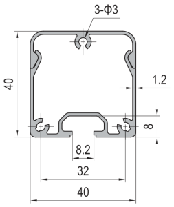 Aluminium Conduit Profile 40×40 mm Cable Duct T-Slot Enclosure
40 x 40 mm aluminium conduit profile in 6063-T5 with a 32 x 8.2…
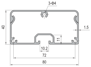 Aluminium Conduit Profile 40×80 mm Large Cable Duct Enclosure
40 x 80 mm aluminium conduit profile in 6063-T5 with a 66 x 11…
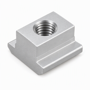 T-Slot Nut 45 Series M8 Hammer Nut for 45×45 Aluminium Extrusion
M8 hammer-head T-slot nut for the 10 mm slot of 45 x 45 mm…
