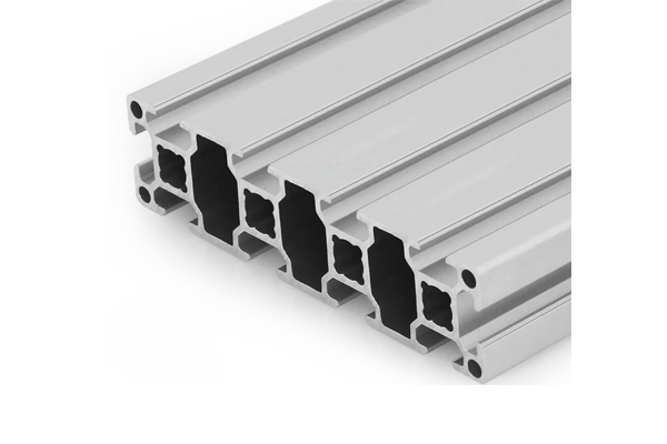
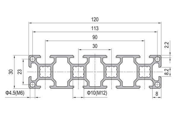
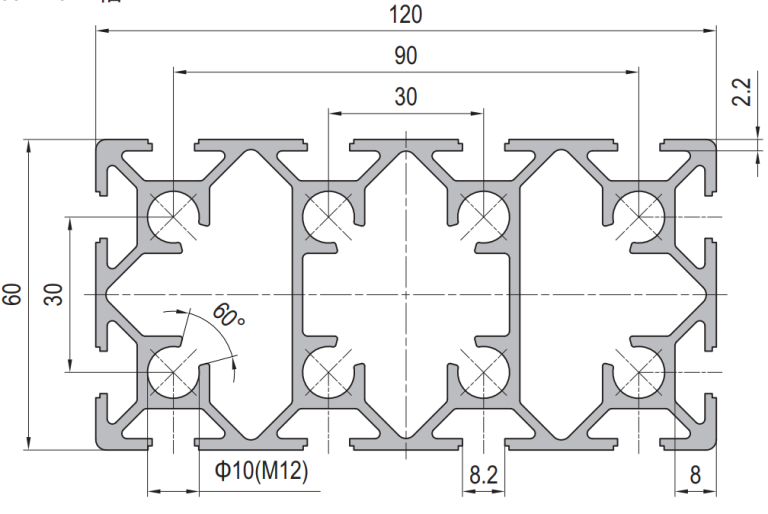
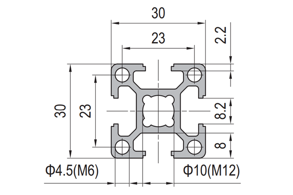
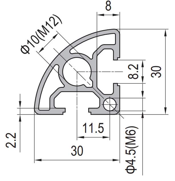
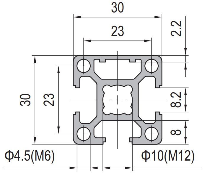
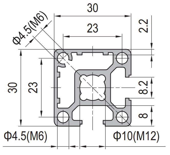
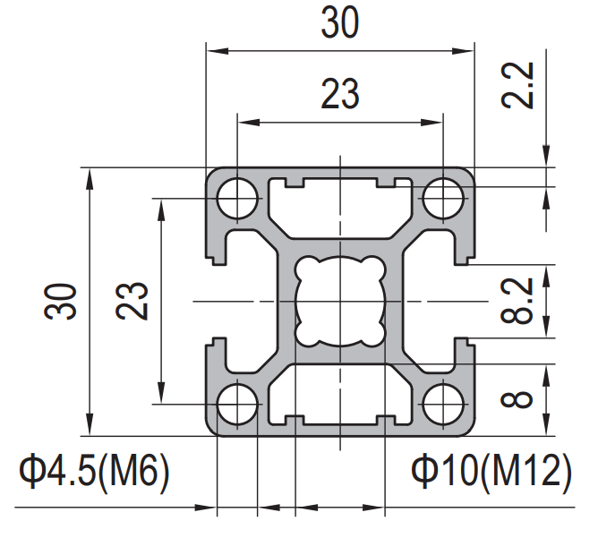
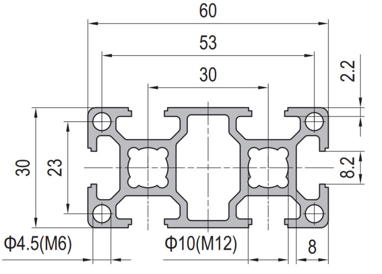
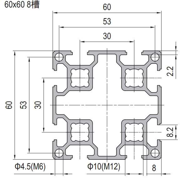
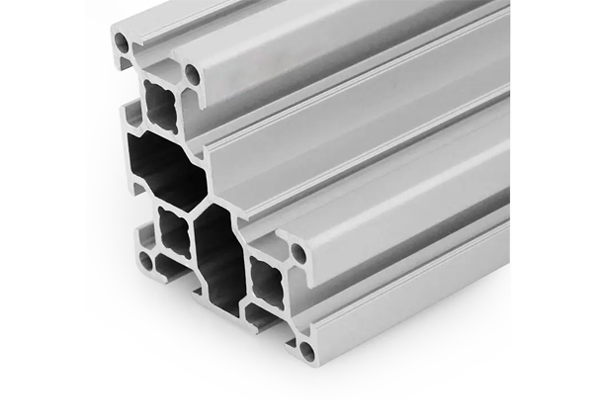
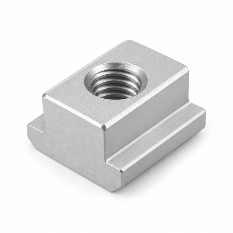
30 series aluminium profiles are slotted extrusions built on a 30 mm module with an 8 mm T-slot. The range covers 30×30, 30×60, 30×90, 30×120, 60×60, 60×90 and 60×120, in several wall variants. They accept M6 and M8 T-nuts, the full 8 mm connector family, and are the standard choice for machine frames, workbenches and guarding where spans stay under roughly 1,200 mm. Some suppliers list this range as PG30.
Below: how the sizes relate to each other, how to choose between them, and how the corners should be built.
What defines the 30 series
Three numbers define it. The module is 30 mm, so the standard square is 30×30 and every larger member is a multiple of that in at least one direction. The slot is 8 mm wide, which sets the fastener: an 8 mm slot takes M6 T-nuts as standard and M8 where the slot geometry allows. The series also fixes the bolt centres on connectors, which is why a 30 series bracket will not bolt onto a 40 series profile without an adaptor.
The 8 mm slot is the reason this series is so widely used. A 6 mm slot limits you to M5 and small brackets, which is fine for a sensor rail but not for a machine base. A 10 mm slot takes heavier fasteners but requires a heavier profile, and the weight and cost rise accordingly. 8 mm is the point where the fastening is genuinely structural while the frame is still light enough to move by hand.
The size family and what each size is for
All of these are 30 series and share the 8 mm slot. They differ in section area, which decides stiffness and weight.
| Section | Slots | Typical role | Notes |
|---|
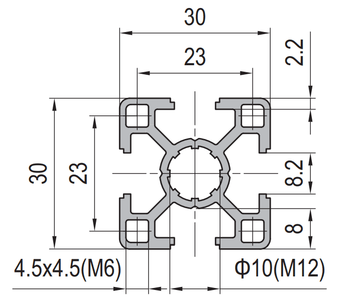
| 30×30 | 4 (also 2 and 3 slot variants) | Light frames, guard posts, panel edges | Available in standard, light and R90 corner variants |
| 30×60 | 6 | Main uprights and horizontals of a bench or small machine frame | The most-used member in the series |
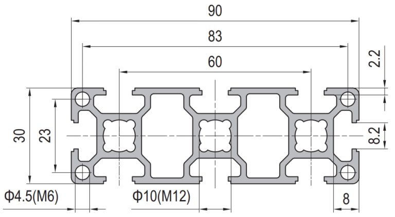
| 30×90 | 8 | Longer spans, frame sides that also carry a panel | Useful where two panels meet a single member |
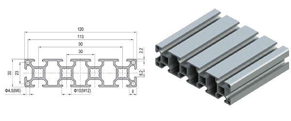
| 30×120 | 10 | Beams over a wide opening, gantry rails at low load | Normally paired with 40 series at the joints |
| 60×60 | 8 | Heavy uprights and compact machine bases | Substantially stiffer than 30×30 for the same length |
| 60×90 / 60×120 | 10–12 | Base frames, machine beds, large platforms | Often the point where 40 series becomes the better economic choice |
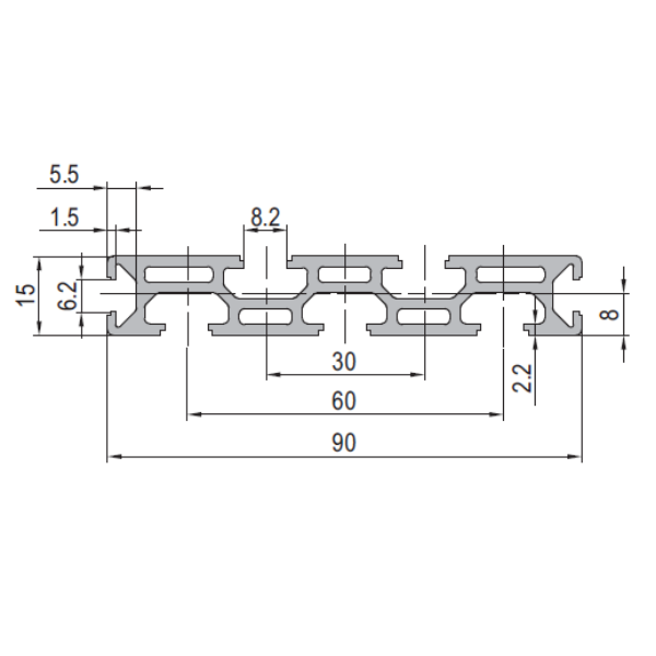
| 15×90 | 7 | Low-profile beams and step edges | Keeps the frame height down where headroom is limited |
Choosing between the sizes
The decision is almost always about span, not about load. A 30×30 member is perfectly capable of carrying a 40 kg panel over 400 mm; over 1,500 mm the same member will sag visibly under its own weight plus a light load. Because deflection rises with the cube of the span, the practical rules are:
- Under 600 mm — 30×30 is normally enough, and the frame stiffness comes from the joints and the bracing rather than the members.
- 600–1,200 mm — use 30×60 as the default. It roughly doubles the section depth in one direction, which is the cheapest way to buy stiffness.
- 1,200–2,000 mm — use 30×90 or 30×120, or add a mid-support. Adding a support is usually cheaper than a bigger profile.
- Beyond 2,000 mm — move to 40 series or 45 series rather than trying to stiffen a 30 series beam.
Practical point: a frame is stiffened far more cheaply by a diagonal brace or a closed panel than by upgrading every member. A single 30×30 diagonal in a rectangular frame can raise the stiffness more than moving every member up one size, at a fraction of the cost and weight.
Building a 30 series corner
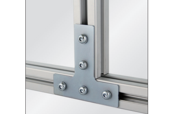
Corners are where 30 series frames succeed or fail, and there are four standard options. The choice is driven by whether the joint has to be invisible and whether it has to be re-openable.
| Method | Appearance | Re-openable | Best for |
|---|
| Anchor connector | Fully hidden inside the slot | Yes, with a hex key | Frames where the outside faces must stay clean; see anchor connectors |
| Die-cast bracket | Visible inside the corner | Yes | Fast assembly, moderate loads; see die-cast brackets |
| Angle bracket | Visible outside or inside | Yes | Retrofitting a brace onto an existing frame; see angle profile brackets |
| Joining plate plus bracket | Visible | Yes | High-load corners where one connector would crush the slot lip; see joining plates |
A single anchor connector in a 30 series corner is adequate for a bench. For a machine base that will see vibration, use two connectors, or a connector plus a plate, so the load is spread over more of the slot lip.
Cutting, tapping and machining
30 series profiles are supplied in 1 m, 2 m, 3 m and 6 m lengths and cut to a cut list on request. Because the module is small, squareness of the cut matters: a 0.5 mm error over a 600 mm member is a visible gap at the corner. We cut to ±0.3 mm with square ends and deburr every cut. Where a frame is supplied as a kit, each member is marked to the cut list.
End taps are the one machining operation worth doing at the factory. An anchor connector needs a tapped or counterbored hole in the end face of one member, and doing that on a bench drill without a jig is slow and easy to get wrong. See CNC machining for the drilling, tapping and milling we can add to the order.
Where 30 series is the right answer
Machine frames and enclosuresThe standard choice where the machine footprint is under about 1.5 m and the frame has to be reconfigurable.
Workbenches and assembly stationsBench tops, light rails, tool holders and ESD earthing all mount in the same 8 mm slot.
Laboratory and test rigsCompact, hand-movable structures that are rebuilt between projects.
Specifying a 30 series order
Give us the section (for example 30×60), the slot width, the finish, the cut list and the quantity. If the frame has to be assembled without a drawing, a photograph of a similar frame plus the overall dimensions is usually enough for us to propose the members and the accessory list. Standard sections are quoted within one working day. Related ranges: 20 series, 40 series, connecting elements, fastening elements and profile accessories.