PG30 30×30 mm Two Slot Type A Aluminium Strut Profile Closed Face T-Slot Extrusion
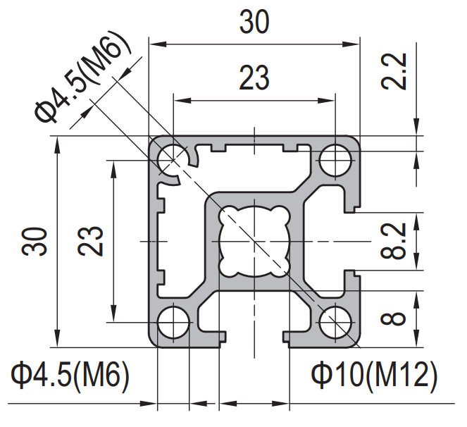
30 x 30 mm Type A two slot PG30 aluminium strut profile in 6063-T5 with 8.2 mm grooves on adjacent faces and two closed faces meeting at one corner. For edge members, seal carriers and datum rails.
| Material | Aluminium |
|---|---|
| Alloy Grade | 6063-T5 |
| Temper | T5 |
| Section Size | 30 x 30 mm |
| Slot | 2 x 8.2 mm groove, 6 mm mouth, adjacent faces, 23 mm pitch, M8 |
| Length | 6 m stock, cut to drawing to +/-0.5 mm |
| Tolerance | EN 755-9 / GB/T 6892, wall +/-0.15 mm |
| Surface | Mill finish / clear anodised / black anodised |
| MOQ | 500 |
| Lead Time | 15-25 days after deposit for mill finish |
| Loading Port | Shanghai / Ningbo |
| Supply Ability | 600 t per month |
| Payment Terms | T/T 30% deposit + 70% before shipment | L/C at sight |
| Trade Terms | FOB | CIF | EXW |
| Certifications | ISO 9001:2015 | EN 755-9 | RoHS | REACH |
Structural framing · PG30 Type A
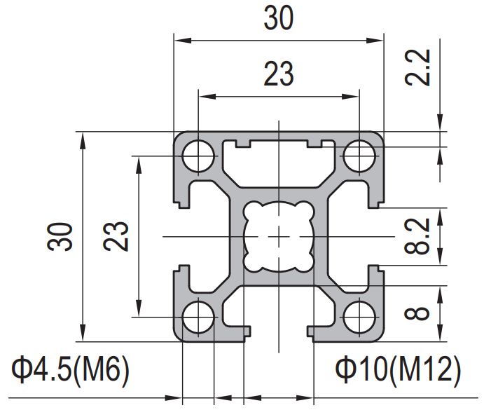
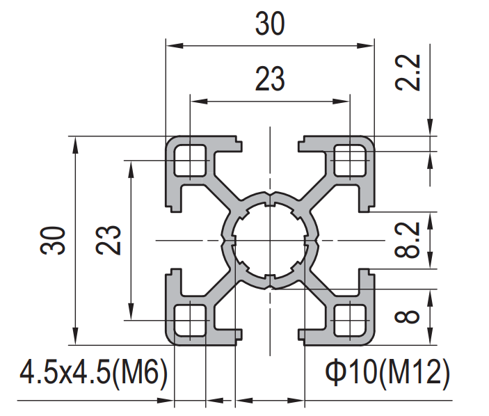
A 30 x 30 mm Type A two-slot strut profile is a square aluminium extrusion with a T-slot on two of its four faces. What makes it Type A is that those two slots are on adjacent faces, not opposite ones: the section therefore carries two solid, unslotted faces, and those two solid faces meet at a single corner. The groove is 8.2 mm with a 6 mm mouth and a 23 mm slot pitch, so it takes 30-series M8 hardware. The centre bore is Ø10 mm tapped M12, the corner holes are Ø4.5 mm tapped M6, and the wall runs 2.2 mm at the flange and 8 mm through the web. We extrude it in 6063-T5 and supply it cut, drilled, tapped or machined.
Most framers choose a section by counting slots and stop there. On a two-slot section that is not enough, because two slots can be arranged two ways and the two arrangements are not equivalent. Type A leaves you a closed corner to work with; Type B leaves you two closed faces on opposite sides. This page is about the closed corner — when you actually need a solid face, and why the asymmetry it creates has to be accounted for in the frame layout.
Adjacent or opposite: what Type A actually means
Take a 30 x 30 square and put a T-slot in two of its four faces. If the two slots are on faces that touch, you have Type A. If they are on faces that face each other, you have Type B. The outside dimensions, the groove, the pitch and the weight are identical, which is why the two are so often confused on a drawing — but the sections behave differently and they cannot be substituted for one another without reworking the frame.
The consequence of the adjacent arrangement is that the two solid faces also touch, meeting at one corner. That corner is the only part of the outside of the section that presents two flat, uninterrupted surfaces at right angles to each other. On a Type B section the two solid faces are on opposite sides and never meet, so there is no such corner.
| Property | Type A (this section) | Type B |
|---|---|---|
| Slot positions | Two adjacent faces | Two opposite faces |
| Closed faces | Two, meeting at one corner | Two, on opposite sides |
| Symmetry | Asymmetric about the face centrelines | Symmetric |
| Best as | Edge member, seal carrier, datum rail | Corner post, upright |
| Slot groove | 8.2 mm, 6 mm mouth | 8.2 mm, 6 mm mouth |
| Slot pitch | 23 mm | 23 mm |
| Centre bore | Ø10 mm, tapped M12 | Ø10 mm, tapped M12 |
| Weight | approx. 0.86 kg/m | approx. 0.86 kg/m |
The closed face is a feature, not a shortage
On an all-slotted section every face is interrupted by a groove, and a groove is a place where a gasket cannot sit flat, a dowel cannot be pressed, and a dial indicator cannot be run. The closed faces on a Type A section solve all three problems at once, and that is the whole reason the section exists.
The asymmetry nobody mentions
Because the two slots sit on adjacent faces, the Type A section is not symmetric about its face centrelines — it is symmetric about the diagonal that runs through the closed corner. In practice that means the closed corner is the stiff side of the member and the open corner is the soft one. A bending load applied across the closed corner is carried by the full depth of the section; the same load applied across the open corner finds less material resisting it.
This matters when a member is used as an edge rail on a frame that also acts as a guard rail or a handrail, because the load arrives from one direction only. Put the closed corner towards the load and the member is noticeably stiffer than the same section the other way round. It is a free improvement — the section costs the same either way — but it has to be decided at the drawing stage, because once the frame is assembled the orientation is locked in.
Drawing rule: on a Type A member, mark the closed corner on the drawing with a small triangle. It fixes both the seal land and the stiff axis in one mark, and it removes the most common assembly error on this section.
Where the closed corner belongs on a real frame
- Put the closed corner on the outside of the frame On a guard, an enclosure or a door frame the closed faces should face outward, where the seal and the visible surface are, and the slots should face inward where the fixings are.
- React the load on the closed corner Where the member carries a one-directional load — a handrail push, a door weight, a panel pull — orient the closed corner towards it. The section is stiffer that way and the fixings are in compression rather than prying.
- Keep the datum corner clear of fixings If the closed corner is used as a datum for setting the frame square, do not put a fixing through it. A bolted joint pulls the surfaces together and destroys the reference you were relying on.
- Never mix A and B in one continuous member The two sections join at the end faces, but the slot pattern does not line up and the closed faces do not meet. Where a frame changes from an edge member to an upright, make the change at a joint, not mid-member.
Frequently asked questions
What is the difference between Type A and Type B 30 x 30?
Only the arrangement of the two slots. Type A has them on adjacent faces and leaves a closed corner; Type B has them on opposite faces and leaves two closed faces on opposite sides. The outside dimensions, groove, pitch and weight are the same.
Can I use it as a corner post?
It is possible but not ideal. A corner post is better served by a symmetric section, because the load arrives from two directions and the symmetric section responds the same way to both. Type A is at its best as an edge member where the load has a known direction.
Does the closed face take a thread?
The 8 mm web behind the closed corner will take a shallow tapped hole for a light duty fixing, but the flange is only 2.2 mm and will not. For anything carrying load, use the Ø4.5 mm corner holes tapped M6 or a T-slot nut in one of the open slots.
Which M8 hardware fits the 8.2 mm groove?
Standard 30-series T-slot nuts, hammer-head bolts and slot covers, all sized for the 8.2 mm groove and the 6 mm mouth. The centre bore takes M12 hardware and the corner holes take M6.
Do you supply it anodised?
Yes, clear or black anodising in a class to suit the application, typically 10 to 20 microns. Where a nut has to slide freely, specify the anodising class at enquiry because the anodic layer does affect a tight sliding fit.
Send the frame drawing with the closed corner marked
Tell us where the seal runs and which way the load arrives. We will confirm whether Type A or Type B is the right section, then quote cut lengths, machining and FOB pricing.
Request a QuoteRelated Products
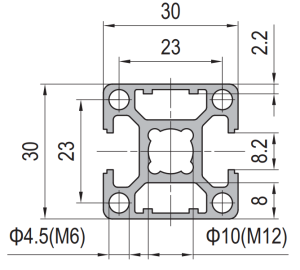 PG30 30×30 mm Two Slot Type B Aluminium Strut Profile Symmetric T-Slot Extrusion for Corner Posts
30 x 30 mm Type B two slot PG30 aluminium strut profile in 6063-T5…
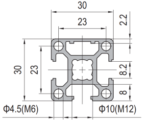 PG30 30×30 mm Three Slot Aluminium Strut Profile Light Frame Column
30 x 30 mm aluminium strut profile with three 8.2 mm T-slots and one…
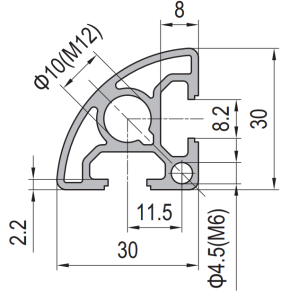 PG30 30×30 mm R90 Two Slot Aluminium Strut Profile Rounded Corner Rail
30 x 30 mm quarter round aluminium profile with one 8.2 mm T-slot on…
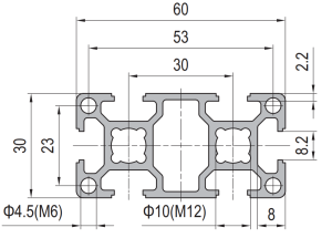 PG30 60×30 mm Six Slot Aluminium Strut Profile Rectangular T-Slot Extrusion for Cabinet Uprights
60 x 30 mm six slot PG30 rectangular aluminium strut profile in 6063-T5 with…
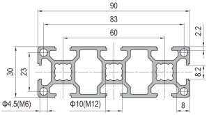 PG30 90×30 mm Eight Slot Aluminium Strut Profile Wide Beam T-Slot Extrusion for Door Frames
90 x 30 mm eight slot PG30 wide beam aluminium strut profile in 6063-T5…
 PG30 90 x 15 mm Seven Slot Aluminium Strut Profile Narrow Multi Slot Rail
90 x 15 mm seven-slot aluminium strut profile with 8.2 mm grooves on a…
 PG30 60×60 mm Eight Slot Aluminium Strut Profile Heavy Duty T-Slot Extrusion for Robot Pedestals
60 x 60 mm eight slot PG30 heavy duty aluminium strut profile in 6063-T5…
 PG30 120 x 60 mm Twelve Slot Aluminium Strut Profile Heavy Frame Beam
A 120 x 60 mm twelve slot PG30 aluminium strut profile at about 5.20…
