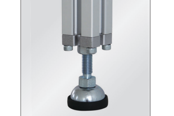
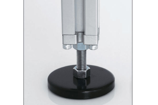
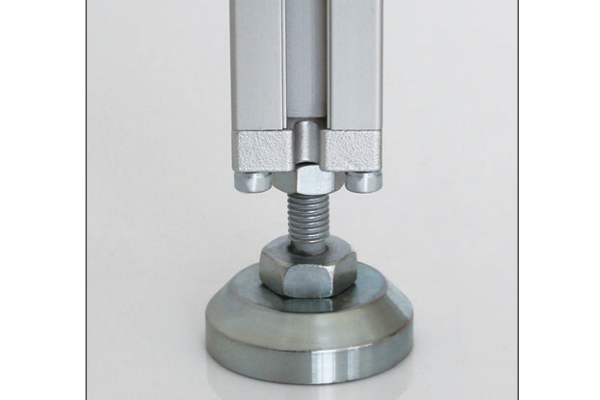
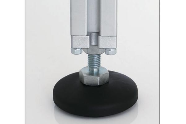
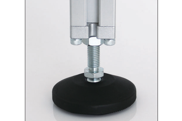
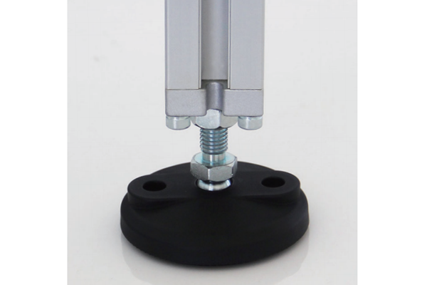
Levelling feet are threaded feet that bolt into the base of an aluminium profile leg and allow the frame height to be adjusted after the frame is standing. They come in thread sizes from about M8 to M20, in fixed and articulated forms, and with plain or anti-vibration pads. They are chosen together with the base plate, because the plate spreads the load and the foot sets the height.
Below: how to size a foot, how to level a four-legged frame so it does not rock, and when levelling is not the right answer at all.
How a levelling foot is sized
Three numbers matter, and getting any of them wrong produces a frame that either will not level or will not hold.
| Number | What it sets | How to choose it |
|---|
| Thread size | The load a single foot can carry, and the adjustment stiffness | Divide the total frame weight by the number of feet, then allow a margin. A bigger thread also means less sensitivity to adjustment |
| Thread length | The range of height adjustment available | Enough to cover the expected floor variation plus the frame build tolerance |
| Pad diameter | The bearing pressure on the floor | Large enough that the floor is not marked or crushed under the full load |
The mistake that shows up most often is an under-sized thread. A foot that is adequate statically can still deflect under a machine load, and a frame on four slightly flexible feet is a frame that will not stay level. Where the frame carries a machine, size the feet for the loaded condition rather than the empty frame.
Fixed, articulated and anti-vibration
| Type | Behaviour | Use it when |
|---|
| Fixed foot | The pad is rigidly attached to the thread, so the pad sits at the angle of the thread | A frame standing on a floor that is flat but not level |
| Articulated foot | The pad swivels, so it sits flat even when the leg is not vertical | Floors with a slope, or a frame that is deliberately not square to the floor |
| Anti-vibration foot | A resilient element between the thread and the pad | Machines with rotating or reciprocating parts, where transmission into the floor matters |
| Bolt-down foot | A foot with a fixing hole through the pad | Frames that have to be levelled and then anchored in the same operation |
Anti-vibration feet are worth understanding rather than specifying by default. They reduce the transmission of vibration into the floor and reduce the noise a machine makes, but they also reduce the stiffness of the connection between the machine and the ground, which can make a lightly built frame move more. Where maximum stiffness is wanted — a machine tool, for example — grouting the base in place is usually better than an anti-vibration foot.
Levelling a four-legged frame
Levelling is a procedure, not an adjustment, and doing it in the wrong order is why frames rock after installation.
- Set the frame down on all four feet first, wound roughly to mid-travel, with the load already on the frame if the machine can be fitted before levelling.
- Level one diagonal, then the other, then go back and re-check the first. Adjusting one foot moves the frame relative to the other three, so the diagonals interact.
- Check with a spirit level in both directions, not just one. A frame can be level front to back and leaning side to side.
- Lock the feet with the locknut the foot is supplied with. An unlocked foot will move under vibration and the frame will go out of level.
- Re-check after the machine has run, and again after a few days. Settling is normal, and it is much cheaper to correct at commissioning than after a production start.
Practical point: if the frame has to be both level and immovable, use a bolt-down foot so levelling and anchoring happen at the same point. Levelling the frame and then anchoring it elsewhere is a reliable way to pull it back out of level.
When levelling is not the answer
There are three situations where adjusting feet is the wrong approach, and where the money is better spent elsewhere.
The floor is badly out of level
If the variation across the frame footprint exceeds the thread travel, no foot will fix it. The options are to pack under a base plate, to build the height difference into the frame legs, or to level the floor area. Feet are designed for the last few millimetres, not for a slope.
The structure needs stiffness, not adjustment
On a machine tool or a structure carrying dynamic loads, four adjustable feet are four flexible connections. A base that is grouted in place, or bolted to a prepared foundation, is stiffer and more stable. Adjustable feet are the right answer for a machine that will be moved; they are the wrong answer for one that will not.
The load is very uneven
Where a frame is heavily loaded at one end, the feet at that end carry most of the load and the others may carry almost none. In that case the number and position of the feet should be reviewed rather than simply fitting larger ones everywhere.
Materials and environments
| Part | Common material | Note |
|---|
| Thread and body | Zinc-plated steel, stainless steel | Stainless for wash-down and outdoor installations |
| Pad | Nylon, polyamide, rubber, steel | Nylon and polyamide protect the floor; rubber adds damping; steel is for maximum load |
| Anti-vibration element | Rubber or a resilient polymer | Specify by the load range, not just the size |
Where a foot is stainless and the frame is aluminium, galvanic corrosion is a consideration in wet or salty conditions. A plastic or nylon isolating pad between the foot and the profile reduces the risk.
Where levelling feet are used
Machine frames and basesLevelling after installation on an industrial floor, usually combined with a base plate. See 60 series aluminium profiles.
Workbenches and assembly stationsLevelling on an uneven workshop floor so the bench top is flat, which matters for assembly work.
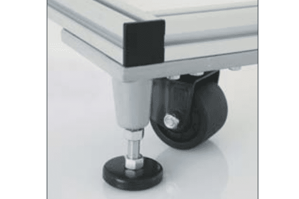
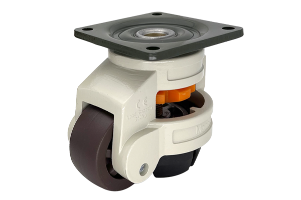
Mobile frames with castorsWound down to take the load off the castors once the frame is in position, so the frame is stable in use.
Laboratory and test rigsLevelling and isolating in one operation, where measurement is affected by floor vibration.
Specifying levelling feet
Give us the profile series, the total frame weight loaded and unloaded, the number of feet, the expected floor variation, whether the frame has to be anchored as well, and whether vibration is a concern. From that we can specify the thread size, the thread length, the pad type and the pad diameter. Where a frame is heavy or carries a machine, tell us the loaded weight — that is the number that decides the foot, not the empty frame weight. Standard feet are quoted within one working day. Related ranges: floor elements, connecting elements, stairway and platform systems, 40 series aluminium profiles and 60 series aluminium profiles.