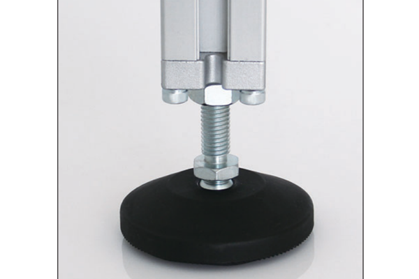
Swivel Ball Foot
Self-aligning levelling foot with a ball-and-socket joint between stem and pad, keeping the pad flat on the floor when the frame leg is not exactly vertical.
| Material | PA6 nylon / steel / stainless steel pad, zinc-plated steel stem |
|---|---|
| Alloy Grade | Not applicable |
| Temper | custom |
| Section Size | Fits profile ends with M8-M16 thread insert |
| Slot | M8 / M10 / M12 / M16 stem thread |
| Length | Stem 40-80 mm; overall height 55-140 mm |
| Tolerance | ±0.3 mm on thread pitch diameter |
| Surface | Zinc plated stem; moulded or stainless pad |
| MOQ | 200 |
| Lead Time | 15-25 days after deposit |
| Loading Port | Shanghai / Ningbo |
| Supply Ability | 150,000 pcs per month |
| Payment Terms | T/T 30% deposit + 70% before shipment | L/C at sight |
| Trade Terms | FOB | CIF | EXW |
| Certifications | ISO 9001:2015 | ISO 14001 | RoHS | REACH |
Levelling feet · Self-aligning
A swivel ball foot has a ball-and-socket joint between the threaded stem and the base pad. That joint lets the pad tilt independently of the stem, so the full face of the pad stays in contact with the floor even when the leg it is fitted to is a few degrees off vertical.
That matters because frames are rarely perfectly square. A welded or bolted frame, a frame standing on a floor with a fall, or a frame whose legs have been cut slightly long on one side all load the foot at an angle. A rigid foot then bears on one edge, which concentrates the load and lets the frame rock. The ball joint removes that edge loading, which is why it is the default foot on adjustable machine frames.
What the ball joint does that a rigid foot cannot
Two things happen when a rigid levelling foot meets an angled leg. The pad tilts off the floor and contacts on one edge, and the stem bends. The edge contact raises the pressure under the pad by an order of magnitude and, on a smooth floor, lets the frame slide; the stem bending puts a permanent set into the thread over time, so the foot loses its adjustment range.
A ball foot absorbs the angle at the joint instead. The pad stays flat, the stem stays straight, and the load is spread over the whole pad face. The angle a ball foot will absorb is typically 10 to 15 degrees off vertical, which covers almost every real frame.
| Stem | Pad diameter | Static load per foot | Typical frame |
|---|---|---|---|
| M8 × 40 mm | 40 mm | 400 kg | Light benches and instrument stands |
| M10 × 50 mm | 50 mm | 600 kg | Workbenches and light machine frames |
| M12 × 60 mm | 60 mm | 1,000 kg | Machine frames and assembly stations |
| M16 × 80 mm | 80 mm | 2,000 kg | Heavy machinery and gantry bases |
Reading the load rating correctly
Choosing the base material
- Nylon (PA6) base is the default. It does not mark epoxy, vinyl or painted floors, it damps vibration, and it is electrically insulating, which matters on equipment frames.
- Steel base with a nylon insert is used where the pad has to resist a side load — a frame that is pushed across a floor — because the steel shell takes the shear rather than the polymer.
- Stainless steel base is specified for wash-down and outdoor installations, and for food and pharma frames where a bare steel pad would corrode.
Practical point: send us the frame weight, the number of legs and the floor the frame stands on. We will return the stem size, the pad diameter and the per-foot rating including the three-foot derating, before you commit to a thread size.
Fitting the foot to the profile
- Decide the fixing method A foot with a plain threaded stem screws into a tapped end or a thread insert in the profile. A foot with a base plate bolts to the end face instead. The profile end detail decides which.
- Tap or insert the end Standard profile ends take an M8, M10, M12 or M16 thread insert pressed or hammered into the core hole. Off-the-shelf feet are supplied to the same thread standard, so no adaptor is needed.
- Set the frame level Adjust the feet under load, not on an unloaded frame, because the frame settles as the weight comes on. Level the frame with the machine in place.
- Lock the adjustment Fit the locking nut and tighten it against the profile end. Without it, vibration walks the foot out of adjustment within weeks.
- Check the pad contact Slide a feeler gauge under the pad. On a ball foot the pad should be flat on the floor; if it is not, the joint is at the limit of its angle and the leg needs shortening rather than more adjustment.
Frequently asked questions
How much angle will a ball foot absorb?
Typically 10 to 15 degrees off vertical, which is more than almost any real frame needs. Beyond that the socket reaches its limit and the pad starts to edge-load again.
Can a ball foot be used on a frame that is moved?
It can, but the load rating has to be halved for a dynamic installation and the base should be steel rather than nylon, because a moving frame puts a side load through the pad.
Do I need a locking nut?
Yes, wherever the frame sees vibration. The nut locks the stem against the profile end so the setting cannot walk.
What thread sizes are available?
M8, M10, M12 and M16 are standard. Metric and UNC threads are both available, and a custom stem length is quoted from the drawing.
Will the nylon pad mark the floor?
No. PA6 nylon is the standard choice for epoxy, vinyl and painted floors because it does not mark or scuff them, and it also damps vibration.
Tell us the frame weight and the floor
Send the frame weight, the number of legs and the floor condition. We will return the stem size, pad diameter and per-foot rating including the three-foot derating, with FOB pricing within one working day.
Request a QuoteRelated Products
 Swivel Foot with Mounting Holes
Levelling foot with a drilled base pad so the frame can be anchored to…
 Nylon Pivot Foot
Levelling foot with a moulded PA6 nylon pivot joint and base, selected for vibration…
 Metal Pivot Foot
Heavy-duty levelling foot with a steel or stainless pivot joint and base, for frames…
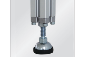 Cup Pivot Foot
Levelling foot moulded as a shallow cup that the profile end seats into, giving…
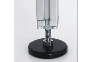 Fixed Foot with Profile Base
Non-adjustable foot that bolts to the profile end at a fixed height, giving higher…
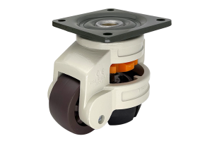 Levelling Castor
Combined castor and levelling foot: move the frame on the wheel, then wind the…
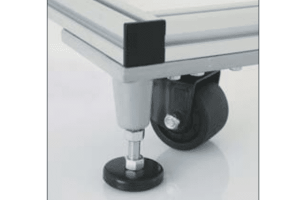 Foot and Castor Components
Spare and replacement components for foot and castor installations — pads, stems, locking nuts,…
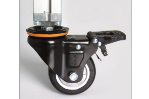 Aluminium Profile Castors
Castors for aluminium profile frames in seven configurations — plate fixed, swivel, braked and…
