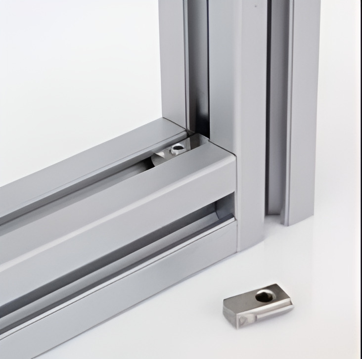
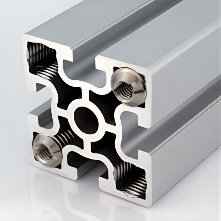
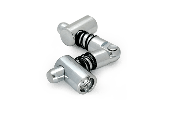
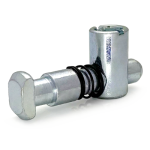
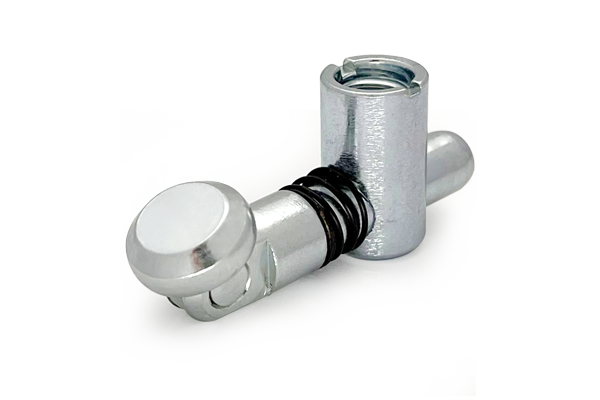
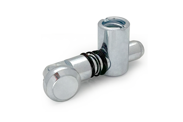
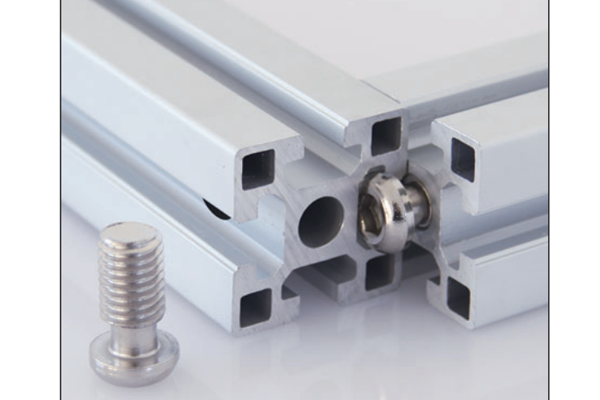
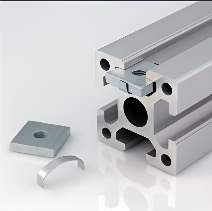
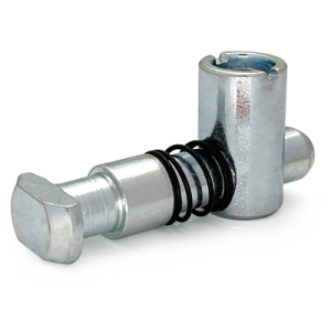
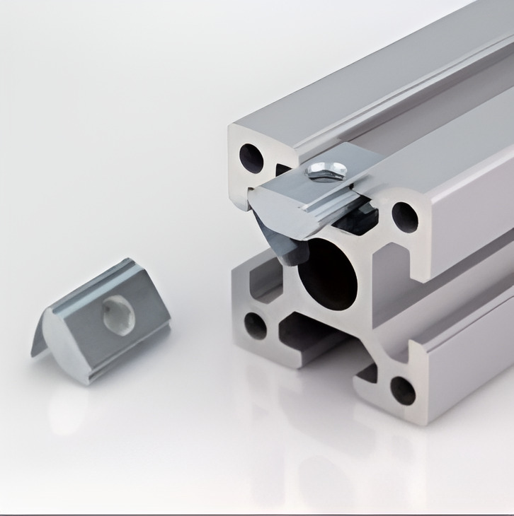
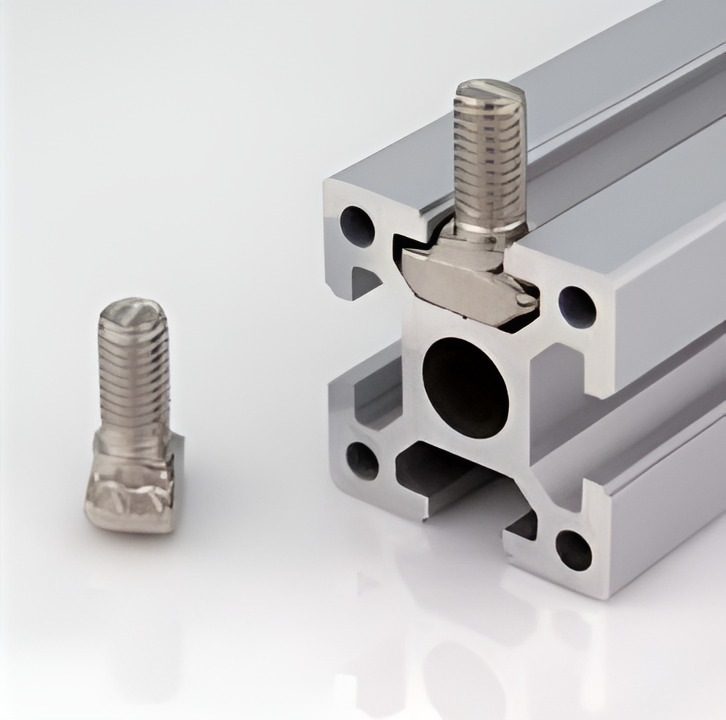
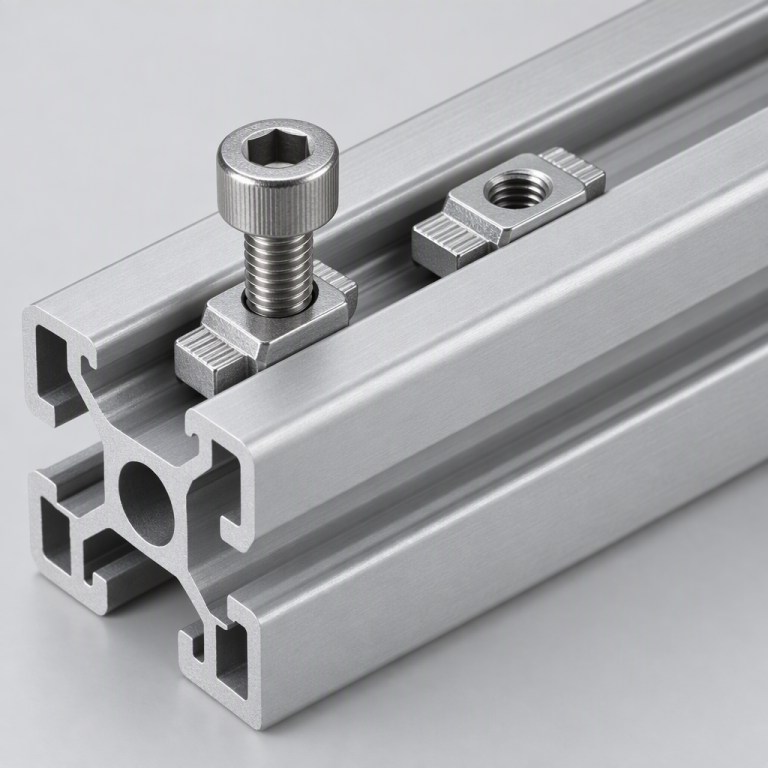
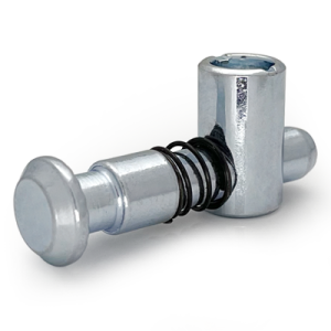
An anchor connector is a two-part concealed joint. A body sits in the slot of the abutting member and an expanding element grips the slot of the through member as the screw is tightened, so the joint is made from inside the profile. The result is a corner with no bracket and no fastener head visible on either outside face. It is the standard joint for furniture, display frames and any structure where the aluminium is meant to be seen.
Below: the assembly sequence, why the abutting member needs an end tap, and the three ways concealed joints fail.
How the joint is made
The mechanism is simple. One member is cut square and its end face is tapped or counterbored. The connector body is inserted into the slot of that member, and the screw passes through the end face into the body. The expanding element, sitting in the slot of the second member, is drawn up as the screw turns and grips the slot lips.
Three consequences follow directly from that mechanism, and they explain almost every practical restriction on concealed joints.
- The abutting member must be machined. Without an end tap or a counterbore there is nothing for the screw to bear against, so an anchor connector cannot be retrofitted to a profile that has already been cut.
- The joint is assembled in a specific order. The connector has to be positioned in the slot before the members come together. A frame built with anchor connectors is assembled once, deliberately, not test-fitted and re-assembled.
- The load goes into the slot lip. The gripping element presses against the inside of the slot, so the lip takes the whole joint load. That is why the number and position of connectors matters more than their size.
The assembly sequence
Getting the order wrong is the single most common reason a concealed frame will not go together.
| Step | Action | Why it matters |
|---|
| 1 | Cut all members square and deburr | A burr stops the end face seating flat and shows as an open corner |
| 2 | Tap or counterbore the ends that take a connector | Do this before assembly; it cannot be done afterwards |
| 3 | Insert the connector body into the abutting member's slot | The body must be in place before the members meet |
| 4 | Offer the members together on a flat surface | A flat surface is what makes the corner square |
| 5 | Tighten progressively, checking the diagonal | Fully tightening one corner before the others pulls the frame out of square |
| 6 | Check and re-tighten after the frame is complete | Earlier joints relax as the frame is closed up |
Practical point: assemble on a flat reference surface and check the diagonals rather than the corner angles. A frame is square when its diagonals are equal, and a tape measure across the diagonals is the fastest quality check there is.
Where an anchor connector is the right choice
Furniture and bench framesNothing should be visible on the outside faces of a bench or a table frame, and the joint has to be re-openable for transport.
Display and exhibition structuresClean anodised faces on every visible side, and the frame can be dismantled and re-used.
Door and window framesUsed with door and window elements where the frame has to look like joinery rather than a machine structure.
Enclosures and cabinetsWhere the outside face carries a panel or is on show, and an internal bracket would be acceptable but a visible one would not.
When not to use one
Concealed joints are not a universal upgrade over visible brackets. There are three situations where a visible bracket is the better engineering answer.
Retrofit and repair
An anchor connector needs an end tap, so it cannot be added to a profile that is already cut. A die-cast bracket or an angle profile bracket can be bolted onto an assembled frame with a hex key, which makes them the right choice for braces, repairs and prototypes.
Very high joint loads
A single anchor connector concentrates the entire joint load on a short length of slot lip. Where a corner carries a machine or a cantilevered load, one connector is not enough: use two, or add a joining plate so the load is spread along the profile.
Frames that will be assembled and disassembled repeatedly
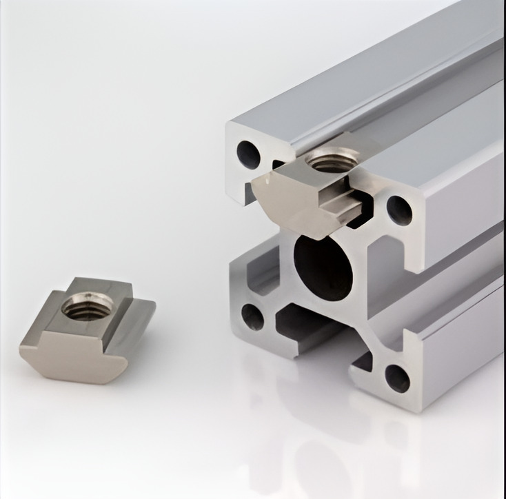
Each assembly cycle works the slot lip. On a frame that is built and struck several times a year, a visible bracket with a replaceable T-nut is more forgiving than a concealed joint that bears directly on the extrusion.
The three ways concealed joints fail
| Failure | Cause | Prevention |
|---|
| The corner will not close | End not tapped deep enough, a burr on the end face, or the connector not seated before assembly | Tap to the depth the connector maker specifies, deburr every end, and check the connector sits flush before offering the members up |
| The joint loosens under vibration | A single connector on a vibrating frame, or insufficient preload | Use two connectors, add a plate, and use a thread-locking compound on dynamic structures |
| The slot lip is crushed | Over-torquing, or a connector sized for a different slot width | Torque to the maker's figure, and confirm the slot width on every member before ordering hardware |
All three are avoidable, and all three are cheaper to avoid than to repair. A crushed slot lip cannot be restored; the member has to be replaced.
Choosing the right connector
Anchor connectors are made in thread sizes to suit the profile series — M6 for 30 series, M8 for 40 and 45 series — and in variants for corners, tees and in-line joints. The variants differ in the angle at which the screw is approached and in whether the connector body sits in the abutting member or the through member. Ordering the correct variant matters more than the brand: a corner connector used at a tee will not seat, and the frame will not pull square.
Confirm three things before ordering: the profile series and slot width, the joint type, and whether the end face will be tapped or counterbored. Related hardware is listed under connecting elements, other connecting elements and fastening elements.
Machining the ends
End taps are the one operation worth doing at the factory. Doing it on a bench drill without a jig produces a tap that is not perpendicular to the end face, and a tap that is off-angle will pull the corner out of square as it tightens. We cut to ±0.3 mm with square ends, deburr, and tap or counterbore to the connector maker's depth in the same order, so the frame assembles without re-work. See CNC machining for the processes available. Related ranges: strut profiles, 30 series, 40 series, die-cast brackets and joining plates.