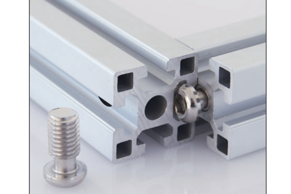
Screw Type Anchor Connector Aluminium Profile Hidden Joint Fastener 30 40 mm Series
Screw type anchor connector for aluminium profile giving a hidden joint with no visible fastener. Fits a tapped end-face hole in 30 and 40 series sections. Machined from bar and electroplated.
| Material | Steel |
|---|---|
| Alloy Grade | Carbon steel, machined from bar |
| Temper | custom |
| Section Size | 30 series / 40 series |
| Slot | Matches the groove of the receiving section |
| Length | By series, to drawing |
| Tolerance | End face squareness within 0.2 mm |
| Surface | Electroplated |
| MOQ | 2000 |
| Lead Time | 18-28 days after deposit |
| Loading Port | Shanghai / Ningbo |
| Supply Ability | 1,000,000 pieces per month |
| Payment Terms | T/T 30% deposit + 70% before shipment | L/C at sight |
| Trade Terms | FOB | CIF | EXW |
| Certifications | ISO 9001:2015 | RoHS | REACH |
Connecting · Anchor connector
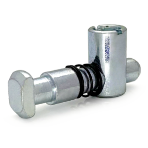
A screw-type anchor connector is a small cylindrical fastener that joins two profiles from inside the section. One end carries a cross bushing that is pushed into a drilled and tapped hole in the end face of the incoming member; the other end is a set screw that bears on the inside of the groove in the receiving member. Turning the set screw pulls the two members together and locks the joint.
The point of it is that nothing is visible. There is no plate on the outside of the corner, no bolt head standing proud of the surface and no fastener in the groove. That matters on frames that are seen rather than only used: display structures, clean room and food area enclosures, machine guards where a protruding bolt head would catch, and any frame where a client has asked for a clean external face.
Why the joint can be hidden
Every other way of joining two profiles leaves a mark on the outside. An angle bracket sits on the outer faces. A T-nut and bolt leaves a bolt head in the groove. A die-cast corner bracket is visible by definition. The anchor connector works because both halves of the fastening are inside the material: the cross bushing is below the end face, and the set screw is below the slot opening.
The cost of that is access. Because the fastener is internal, it can only be reached and tightened through the end face of one member before the frame is closed up. That is what dictates the assembly order on an anchor-connector frame, and it is the single thing most often got wrong on a first build.
The four-step installation
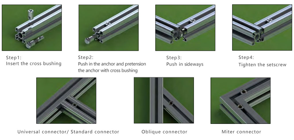
- Insert the cross bushing The cross bushing goes into the drilled and tapped hole in the end face of the member that will be pulled in. It is a light push fit and should seat fully without being driven, because the aluminium around it is thin and will deform if forced.
- Push in the anchor and pretension it The anchor is pushed into the same hole and turned so its thread picks up in the bushing. Pretension by hand at this stage, not with a driver. The purpose is to hold the assembly together while the frame is offered up, not to clamp anything yet.
- Push the member in sideways The prepared member is offered to the receiving member and slid in from the side, so the anchor body enters the groove of the receiving section. It has to go in from the side because the anchor cannot pass the slot opening once it is assembled.
- Tighten the set screw The set screw is turned to expand the anchor against the inside of the groove and pull the two faces together. Tighten to the specified torque and stop. The joint relies on friction between the anchor and the groove, so over-torque deforms the groove rather than strengthening the joint.
The end face has to be right
An anchor connector is unforgiving about the hole it goes into. The cross bushing has to be concentric with the section, the hole has to be on the centre line of the groove it will bear against, and the end face has to be square to the axis. Get any of those wrong and the anchor either will not enter, or it enters and pulls the joint out of square.
The requirement is not difficult to meet, but it does have to be planned. A frame designed for anchor connectors should be cut on a machine that produces a square end and drilled on a jig, not marked and drilled by hand on site.
| Feature | Requirement | Consequence of missing it |
|---|---|---|
| End face squareness | Within 0.2 mm across the section | Joint pulls out of square, visible gap at the corner |
| Hole position | On the groove centre line, within 0.15 mm | Anchor bears on the groove flank, low holding force |
| Hole depth | Full anchor length plus 2 mm | Anchor bottoms out before the faces meet |
| Tap condition | Clean, full thread, no swarf | Cross-threading, anchor cannot be pretensioned |
| Cut finish | Burr-free on the end face and inside the hole | Anchor binds on entry, bushing will not seat |
How the connector is made
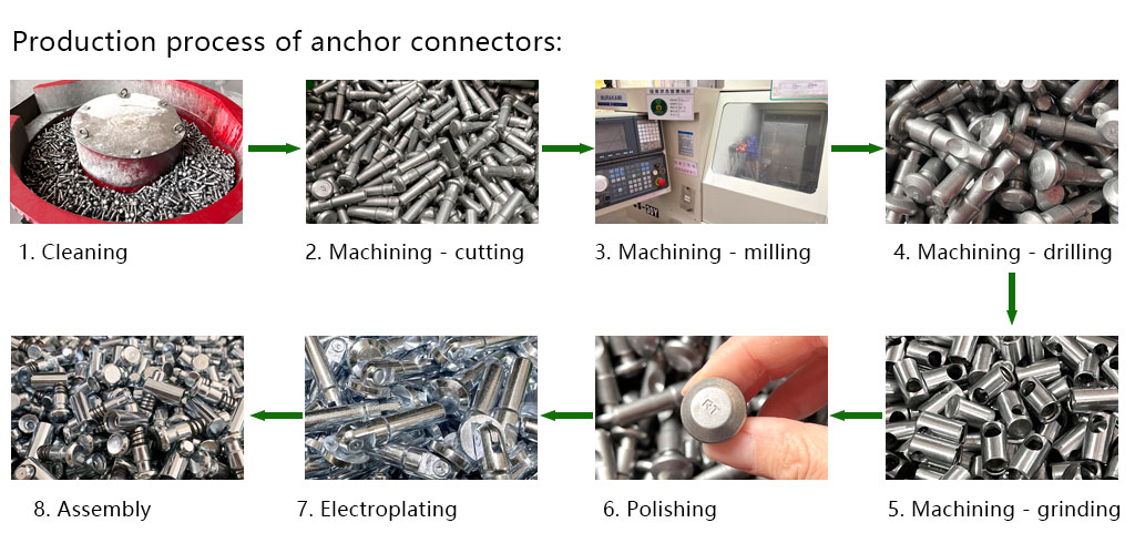
The connector is machined from bar stock rather than cast, because the wall of the anchor has to be thin enough to expand inside the groove and strong enough not to split when the set screw is turned. Machining in several operations keeps the bore concentric with the outside diameter, which is what allows the anchor to expand evenly and grip the full width of the groove.
Plating matters more than it looks. The anchor is a steel part buried inside an aluminium section, and any moisture that reaches it has nowhere to drain. Electroplating with a full passivate is what stops the anchor corroding in place and seizing in the bushing.
Where a hidden joint is worth the extra work
Anchor connector or an angle bracket? Use the anchor connector where the outside of the frame has to stay clean and the end faces can be drilled and tapped before assembly. Use an angle bracket where the frame is functional, the joint has to be adjustable, or the frame will be taken apart again. The bracket is faster and reversible; the anchor is cleaner and permanent.
Frequently asked questions
What is a screw type anchor connector?
A cylindrical fastener that joins two profiles from inside the section. A cross bushing goes into a tapped hole in the end face of one member and a set screw expands the anchor against the groove of the other, so no fastener is visible on the outside of the frame.
Which series does it suit?
30 series and 40 series sections are the standard sizes. The anchor must match both the groove it expands into and the end-face hole it is tapped into, so give us the section you are using rather than the thread size alone.
Can I fit it on site with hand tools?
Only if the end faces were drilled and tapped before delivery. The tapping is the part that needs a jig; the assembly itself is a hand operation. Cutting, marking and drilling a frame on site will not hold the tolerance the connector needs.
Does the joint come apart again?
It can be loosened and re-tightened, but it is not designed as a frequently dismantled joint. Each cycle works the cross bushing in the aluminium, and after several cycles the hold falls away. For a frame that is taken apart regularly, use an angle bracket instead.
What torque should the set screw be tightened to?
Tighten to the figure we supply with the connector for your section, and stop there. The anchor grips by friction against the groove; past the specified torque it deforms the groove and the holding force falls rather than rising.
Tell us the section and we will confirm the connector
Send the profile you are using and how you plan to prepare the end face. We will confirm the correct anchor connector, quote the bulk price and supply samples with the hole specification for a trial frame.
Request a QuoteRelated Products
 Miter Connector Model P 45 Degree Corner Joint for 30 and 40 mm Aluminium Profiles
Miter connector Model P, a hidden 45 degree corner joint for 30 and 40…
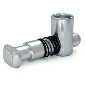 Standard Connector Model C Aluminium Profile Corner Joint 90 Degree 30 40 mm Series
Model C standard connector for a 90 degree corner in aluminium profile with both…
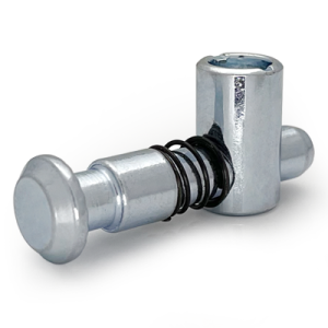 Universal Connector Aluminium Profile Adjustable Angle Joint Fastener M8 30 40 mm
Universal connector for aluminium profile with an angle set during assembly. Suits diagonal braces,…
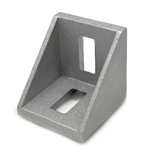 Die Cast Bracket for 20 to 50 mm Series Aluminium Profiles Corner
Die cast zinc alloy corner bracket for 20, 30, 40, 45 and 50 series…
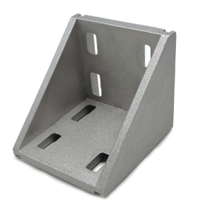 Heavy Duty Die Cast Corner Bracket for Aluminium Profile 60 80 90 100 mm Series
Heavy duty die cast corner bracket for large aluminium profile frames in 60, 80,…
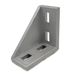 Rectangular Die Cast Corner Bracket Aluminium Profile 30×60 40×80 45×90 50×100 mm
Rectangular die cast corner bracket with unequal legs for aluminium profile frames built from…
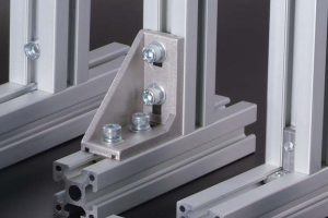 Aluminium Extrusion Connector System for 20×20 to 100×100 mm T-Slot Frames
A complete aluminium extrusion connector system covering visible brackets, hidden inner brackets, cubic corner…
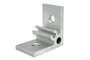 Aluminium Angle Profile Bracket 35x35x4 mm M6 Corner Brace for 20 and 30 Series Profiles
A 35 x 35 x 4 mm aluminium angle profile bracket for 20 and…
