Aluminium Extrusion Connector System for 20×20 to 100×100 mm T-Slot Frames
A complete aluminium extrusion connector system covering visible brackets, hidden inner brackets, cubic corner blocks, screw connectors and end face connectors for 20 to 50 series T-slot profiles.
| Material | Aluminium, zinc alloy and steel by family |
|---|---|
| Alloy Grade | 6063-T5 profile, ADC12 die casting, 304 stainless inserts |
| Temper | custom |
| Section Size | Suits 6.2, 8.2 and 10.2 mm grooves across 20 to 50 series |
| Slot | 6.2, 8.2 and 10.2 mm grooves, M5 to M10 hardware |
| Length | Stocked to suit standard profile series, no cutting required |
| Tolerance | Die casting and machining to ISO 8062 and ISO 2768-m |
| Surface | Mill finish / anodised / zinc plated / black oxide |
| MOQ | 500 |
| Lead Time | 15-25 days after deposit |
| Loading Port | Shanghai / Ningbo |
| Supply Ability | 2 million pieces per month |
| Payment Terms | T/T 30% deposit + 70% before shipment | L/C at sight |
| Trade Terms | FOB | CIF | EXW |
| Certifications | ISO 9001:2015 | RoHS | REACH |
Connecting elements · Joint selection
An aluminium extrusion connector system is the set of joints that hold a T-slot frame together, and the five families are the visible bracket, the hidden inner bracket, the cubic corner block, the screw connector and the end face connector. They are not interchangeable, and they are not ranked from cheap to expensive — each one solves a different problem. Choosing the wrong family is the most common reason a frame ends up either ugly, loose or impossible to take apart.
There is one fact that governs every joint in the system: the capacity of a T-slot connection is set by the slot, not by the bolt. An M8 grade 8.8 bolt will carry around 15 kN in tension, but an M8 hammer-head nut pulls out of a 40 series groove at about 1.5 to 2.2 kN, and the tightening torque ceiling is only about 15 N m. Anything that has to carry a real load therefore has to move the load out of the slot and into the section, which is exactly what the cubic, screw and end face families do.
Four questions, asked in this order
The order matters. Asking them in a different sequence leads to a joint that works structurally but cannot be serviced, which is the worst of both worlds.
The five families compared
| Joint family | Visible or hidden | Re-usable | How the load is carried | Relative cost |
|---|---|---|---|---|
| Die-cast or angle bracket | Visible | Yes, many times | Through the slot in shear, with the bracket in bending | Low |
| Inner bracket with top thread | Fully hidden | Yes | Set screw jams the bracket into the groove | Low to medium |
| Cubic connector | Visible but neat | Yes, many times | A solid block in three-axis compression | Medium |
| Screw connector | Fully hidden | Limited | Self-tapping thread in the profile core hole | Lowest |
| End face connector | Fully hidden | Yes | Bolt in tension into a tapped end face | Medium |
Read that table as a set of trade-offs rather than a ranking. The screw connector is the cheapest and the neatest, and it is the one you cannot take apart. The end face connector is the strongest and it needs the end of the profile to be machined. The bracket is the most flexible and the most visible.
When to choose each one
Visible bracket — the default for anything that will be modified
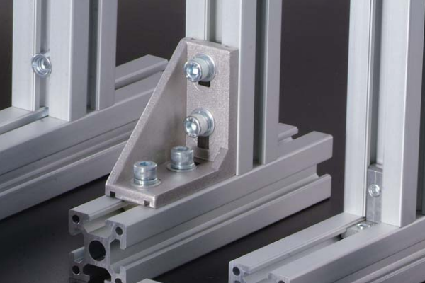
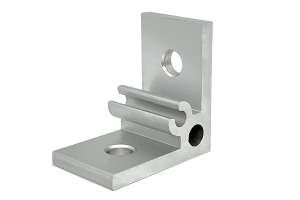
A die-cast or angle bracket bolted through the slot is the joint you can undo with a hex key on a finished frame. That makes it the right answer for guarding, workstations, shelving and anything that is expected to change. The angle profile brackets range covers the small sizes from 35 x 35 x 4 mm upwards, and the die-cast brackets cover the moulded corner pieces with a locating spigot that sits in the slot.
The limit is appearance and stiffness. A bracket is in bending across the corner, so the joint is never as rigid as a connection that puts the member end in compression. On a frame that has to hold a machine tool position, a bracket corner will move under load.
Inner bracket with top thread — the answer for visible frames
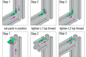
An inner bracket slides into the groove of both members and a set screw is driven down onto the groove floor to jam it in place. Nothing shows on the outside. It is available with M5, M6 and M8 threads to suit 6.2, 8.2 and 10.2 mm groove cavities, so one design covers the 20, 30 and 40 series. On a display frame, a door frame or an enclosure where every face is seen, this is the only family that gives a completely clean surface without machining the profile ends.
Cubic connector — three members at one node
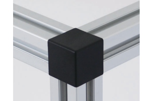
A cubic connector is a solid block with bores on three faces, used where three members meet at a corner. Because the block is in compression rather than in bending, the node is far stiffer than three brackets would be, and it uses fewer parts. The 20 series version is a 20 x 20 x 20 mm cube with three 14.5 mm bores and a 26 mm centre; the 45 series version is 45 x 45 x 45 mm on the same geometry. A clip-on ABS cap covers the exposed face.
Screw connector — the cheapest hidden joint
A screw connector is driven into the core hole at the end of one profile and forms its own thread in the aluminium. It is the cheapest way to hide a joint, and it is the least forgiving. Re-using the formed thread more than two or three times loses its grip, so it belongs on a frame that is assembled once and left alone. Use it on production frames, not on prototypes.
End face connector — the strongest hidden joint
An end face connector bolts into a tapped hole in the end of the profile, with a spring clip to hold the position while you assemble. Because the bolt is in tension into the section rather than in shear through the slot, the capacity is set by the thread rather than by the groove. This is the joint to use wherever a member is pulled, wherever the frame has to be rigid, and wherever a bracket has already proved too flexible. It shares the design space with the anchor connectors, which do the same job with a different locking mechanism.
Mixing families on one frame
A real frame uses two or three families at once, and the rule for combining them is simple. Put the stiff, hidden joints where the load is and the brackets where the adjustment is. A typical machine guard frame uses end face connectors or anchor connectors at the four base corners, brackets on the panel-retention nodes, and inner brackets on the one face that the customer sees.
The one combination to avoid is mixing a screw connector with anything that expects to be re-tightened. Once a self-tapping connector has formed its thread, the joint is effectively permanent, and treating it as adjustable is how a frame ends up with stripped threads in the core hole.
Specify the joint before you specify the frame. The joint choice decides whether the profile ends need machining, whether the slot has to be accessible from a particular side, and whether the frame can be assembled in the order you want. Changing it later means re-cutting members.
Frequently asked questions
Which connector is strongest?
The end face connector, because the load goes into the section through a tapped thread rather than through the slot lip. A cubic connector is next, since the block is in compression. A bracket joint is the weakest of the three because the bracket itself is in bending.
Can I use a bracket joint for a load-bearing corner?
Yes, within limits. A bracket bolted through the slot is limited by the slot pull-out of about 1.5 to 2.2 kN per M8 nut in a 40 series profile, and by the bending of the bracket itself. For a machine frame carrying real load, use an end face or cubic joint at that corner instead.
What is the difference between an anchor connector and an end connector?
Both fix into the end of a profile. The anchor connector expands or locks inside the core hole; the end connector uses a bolt with a spring clip to hold position. The end connector is easier to assemble and the anchor connector generally gives a more rigid joint.
Do hidden joints need special profile machining?
Some do. An inner bracket needs nothing beyond a clean cut end. A screw connector needs a drilled core hole of the right diameter. An end face connector needs the end faced square and a tapped hole. Tell us which joint you are using and we will machine the ends to suit.
Can I mix 30 and 40 series connectors on one frame?
No. The groove widths differ, so a 40 series nut will not enter a 30 series slot and the brackets are sized for different slot pitches. Keep one series per frame, or use a transition plate where two series have to meet.
Send the frame drawing and the joints that must come apart
Tell us which nodes are load-bearing, which faces are visible and which joints have to be re-openable. We will select the connector family for each node and quote the hardware as a kit.
Request a QuoteRelated Products
 Aluminium Angle Profile Bracket 35x35x4 mm M6 Corner Brace for 20 and 30 Series Profiles
A 35 x 35 x 4 mm aluminium angle profile bracket for 20 and…
 Aluminium Inner Bracket with Top Thread M5 M6 M8 for 20 to 40 mm T-Slot Profiles
A hidden inner bracket with top thread for aluminium T-slot profiles, supplied in M5…
 Aluminium Cubic Connector 2020 20×20 mm Three-Way Corner Joint with ABS Cap
A 20 x 20 x 20 mm three-way cubic corner connector for 20 series…
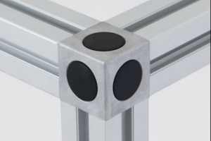 Cubic Connector 4545 45x45x45 mm Three-Way Aluminium Corner Joint Block for 45 Series
A 45 x 45 x 45 mm three-way cubic corner connector for 45 series…
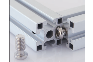 Self-Tapping Screw Connector for Aluminium Profile M6 M8 M10 to 50 mm Series
A self-tapping screw connector for aluminium profiles in M6, M8 and M10. Forms its…
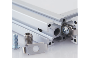 End Face Connector for Aluminium Profile M8 M10 up to 50 mm Series with Spring Clip
An end face connector for aluminium profiles in M8 and M10 with a spring…
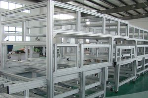 Aluminium Profile Shelf System 40×40 mm T-Slot Uprights for Workshop Racking
A bolted aluminium profile shelf system in 40 x 40 mm T-slot uprights and…
Aluminium Framing Extrusion Kit 40×40 mm 40 Series Cut List for Machine Frames
A cut-to-length aluminium framing extrusion kit in the 40 series: profile cut to a…
