PG30 30×30 mm R90 Two Slot Aluminium Strut Profile Rounded Corner Rail
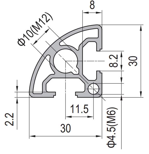
30 x 30 mm quarter round aluminium profile with one 8.2 mm T-slot on each flat face and a swept corner. Used for exposed frame edges where a sharp aluminium arris is not acceptable.
| Material | Aluminium |
|---|---|
| Alloy Grade | 6063-T5 |
| Temper | T5 |
| Section Size | 30 x 30 mm quarter round, swept corner |
| Slot | 2 x 8.2 mm groove, 6 mm mouth, 11.5 mm pitch, M8, one per flat face |
| Length | 6 m stock, cut to corner lengths to +/-0.5 mm |
| Tolerance | EN 755-9 / GB/T 6892, wall +/-0.15 mm |
| Surface | Mill finish / clear anodised / black anodised |
| MOQ | Made to order; trial lengths available |
| Lead Time | Typically 2 to 3 weeks for mill finish, about a week longer for anodising |
| Loading Port | Shanghai, Ningbo, Qingdao |
| Supply Ability | Extrusion, cutting, mitring, tapping and anodising in house |
| Payment Terms | T/T 30 per cent deposit, balance against copy of bill of lading; L/C at sight for larger orders |
| Trade Terms | FOB, CIF, CFR, EXW |
| Certifications | Mill certificate to EN 10204 3.1 on request, RoHS and REACH declarations |
01What is the 30 x 30 mm R90 quarter round profile?
What is a quarter round section?
It is a 30 x 30 mm profile where one corner is swept to a large radius instead of being left as a sharp 90 degree arris. The section still measures 30 mm on both flat faces, so it sits flush in a frame, but the corner that faces the outside of the frame is a continuous curve.
Why would I use this instead of a square 30 x 30 mm section?
For the same reason a machine guard has rounded corners: the corner is the part that gets touched, cleaned and caught on. A swept corner removes the arris without needing a separate trim strip or corner cap. It also means the frame edge is a single continuous surface in the finish, so an anodised frame does not show a bright edge line where the two faces meet.
What are the two slots for?
One slot on each flat face. That is enough for a corner rail, because the other two faces are the ones that meet the rest of the frame and are normally fixed with end connections or brackets rather than with slot fixings.
02Section data
| Item | Value | Note |
|---|---|---|
| Envelope | 30 x 30 mm | quarter round, one swept corner |
| Slots | 2 | 8.2 mm groove, 6 mm mouth |
| Slot pitch | 11.5 mm | centre to centre |
| Corner | swept, R90 nominal | continuous arc, no arris |
| Slot nut | M6 | standard 30 series |
| End thread | M8 | in the flat end wall |
| Wall | 1.5 to 1.8 mm | thinner than the square section |
| Weight | approx. 0.62 kg/m | as published |
| Alloy | 6063-T5 | EN AW-6063 |
| Standard | EN 755-9 / GB/T 6892 | wall tolerance +/-0.15 mm |
| Length | 6 m stock | cut to corner lengths to +/-0.5 mm |
The 11.5 mm slot pitch is the number to watch. It is much tighter than the 23 mm pitch of the square 30 x 30 section, because the two slots sit on adjacent faces of a small swept section rather than opposite each other. That leaves less than 6 mm of metal between the two slot roots.
03The narrow pitch is the whole design constraint
On a square 30 x 30 section the slots sit opposite each other with 23 mm between centres, so there is a solid web of metal running down the middle of the profile between the two slot roots. On this quarter round section the two slots sit on adjacent faces, only 11.5 mm apart, and the swept corner runs between them.
That changes how the section behaves under load. The web between two slot roots is what resists the clamping force from a slot nut; when the roots are only 11.5 mm apart, that web is thin. Tighten a slot nut too hard and the lips on both slots move together, and the corner opens. The section does not fail dramatically, but the joint loses its preload and the frame goes slack.
The practical rule is to treat this section as a trim and edge member, not a structural node. It is the right choice for a corner rail, a door edge, a display frame or a handrail where the corner is seen. It is the wrong choice for the corner of a load bearing frame, where the square section with its 23 mm pitch belongs.
| Duty | Suitable | Reason |
|---|---|---|
| Corner rail on a light frame | yes | load is carried by the panels and the end connections |
| Door or hatch edge | yes | the swept corner is the wear surface |
| Handrail or trolley edge | yes | the rounded face is the one that is gripped |
| Display and exhibition frame | yes | appearance is the requirement |
| Load bearing corner node | no | use the square section with the 23 mm pitch |
| Member spanning more than 800 mm | no | too little material in the section |
There is one more consequence of the sweep worth knowing before you draw the frame. Because the corner is a curve, the datum for the frame changes. On a square section you can lay the member flat on a table and use two faces as datums. On a quarter round you have one flat face and one flat face at 90 degrees, with an arc between them. Dimension the frame from the slot centres, not from the swept corner, or the frame will come out a few tenths out of square at every joint.
04Choosing between the R90 rail and the square 30 mm section
Quarter round R90 rail
- The corner of the frame is seen and touched
- You want a rounded edge without a separate trim strip
- The member is an edge or trim, not a load path
- You want the anodised finish to run continuously around the corner
- Two slots on the two exposed faces are enough
Square 30 x 30 mm section
- The member carries load between joints
- You need the 23 mm pitch and the solid web between slots
- Accessories must bolt to three or four faces
- The corner is hidden inside cladding or a panel
- You want the stiffest 30 mm section available
The two are normally used on the same frame: square section for the structural nodes, R90 rail along the edges that people see and touch. Specify them on one order so the cut list is optimised across both.
05Failure modes to design out
| What goes wrong | Why it happens | Design it out by |
|---|---|---|
| Slot lips deform on both slots at once | 11.5 mm pitch leaves a thin web between the two slot roots | torque to the slot nut supplier’s figure, never by feel |
| Frame runs out of square | the swept corner is not a usable datum | dimension from slot centres and assemble on a flat table |
| Corner looks dull after anodising | the arc scatters light differently from the flat faces | specify a matte etch rather than a bright anodise |
| Rail dents at the corner | the swept wall is thinner than the square section | fit corner caps on trolleys and handrails that take knocks |
| Accessory does not sit flat | a bracket designed for a square section is used on the arc | use brackets that bear on the flat faces only |
06What to check before you order
Procurement checklist for the R90 quarter round rail
- Confirm the corner orientation: which of the four corners of the frame the sweep is on, and whether it faces out on both sides or only one.
- Confirm the cut length and mitre angle. A mitred end on a swept section must be cut from the same datum as the frame corner.
- Confirm the thread at the ends: M8 in the flat end wall is standard, but state the depth and whether it is through.
- Confirm the finish. A matte etch is recommended so the arc does not show as a bright band.
- Confirm the accessory series. 30 series slot nuts only; 40 series will not fit the 6 mm mouth.
- Confirm the quantity in metres, allowing for the mitre waste at each end of a 6 m bar.
07Terms used on this page
- Quarter round
- A square section with one corner swept to a large radius instead of a sharp arris.
- Arris
- The sharp edge where two faces meet. Removing it is the whole point of the swept corner.
- Slot pitch
- The distance between slot centres. On this section it is 11.5 mm, against 23 mm on the square section.
- Slot root
- The widest part of the groove, behind the mouth. The web of metal between two slot roots carries the clamping load.
- Preload
- The tension a tightened bolt puts into a joint. If the lips deform, preload is lost and the joint goes slack.
- Datum
- The face or axis a frame is measured from. On a swept section, use the slot centres.
08Questions buyers ask
What is the quarter round section used for?
Exposed edges on light frames: corner rails, door and hatch edges, handrails, trolley edges, and display or exhibition frame corners.
How many slots does it have?
Two, one on each flat face, on an 11.5 mm pitch. The swept corner itself has no slot.
Can it carry the same load as the square 30 x 30 mm section?
No. It has less material and a tighter slot pitch, so it is a trim and edge member. Use the square section for load bearing nodes.
What thread sizes does it take?
M6 slot nuts in the grooves, and M8 tapped into the flat end wall.
Is it available in other radii?
The radius is set by existing tooling. A different radius means a new die and a tooling charge, which only pays back at container scale.
What is the weight per metre?
Approximately 0.62 kg/m, so a 6 m bar is about 3.7 kg.
Can it be supplied mitred?
Yes. State the mitre angle and the datum face on the drawing, and the arc will run continuously through the corner of the finished frame.
What we need to quote this section
- The section reference and the corner orientation in the finished frame.
- The cut list with lengths and mitre angles.
- The end preparation: square cut, mitre, or tapped ends with the thread size.
- The finish: mill, clear anodised, or black anodised, with a note on whether a matte etch is acceptable.
- The quantity in metres or pieces, with the mitre waste allowed for.
- Any sample requirement before the production run.
Quotations separate extrusion, cutting, mitring, tapping and finishing, so the cost of each step is visible and a design change can be priced before it is made. Browse the full aluminium profile catalogue and the 30 series aluminium profiles range for related sections.
Need a rounded corner rail quoted?
Send the section, the mitre angle and the finish. We quote extrusion, cutting, tapping and anodising as separate lines.
Request a quotationRelated Products
 PG30 60×30 mm Six Slot Aluminium Strut Profile Rectangular T-Slot Extrusion for Cabinet Uprights
60 x 30 mm six slot PG30 rectangular aluminium strut profile in 6063-T5 with…
 PG30 90×30 mm Eight Slot Aluminium Strut Profile Wide Beam T-Slot Extrusion for Door Frames
90 x 30 mm eight slot PG30 wide beam aluminium strut profile in 6063-T5…
 PG30 90 x 15 mm Seven Slot Aluminium Strut Profile Narrow Multi Slot Rail
90 x 15 mm seven-slot aluminium strut profile with 8.2 mm grooves on a…
 PG30 60×60 mm Eight Slot Aluminium Strut Profile Heavy Duty T-Slot Extrusion for Robot Pedestals
60 x 60 mm eight slot PG30 heavy duty aluminium strut profile in 6063-T5…
 PG30 120 x 60 mm Twelve Slot Aluminium Strut Profile Heavy Frame Beam
A 120 x 60 mm twelve slot PG30 aluminium strut profile at about 5.20…
 PG40 40 x 40 mm Single Slot Aluminium Strut Profile Guide Rail Base
40 x 40 mm single-slot aluminium strut profile with one 10.2 mm groove on…
 PG40 40 x 40 mm Two Slot Type A Aluminium Strut Profile Guide Rail
40 x 40 mm Type A two slot asymmetric PG40 aluminium strut profile in…
 PG40 40 x 40 mm Two Slot Type B Aluminium Strut Profile Opposite Rail
40 x 40 mm Type B two-slot aluminium strut profile with two 10.2 mm…
