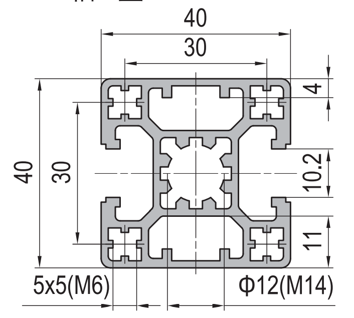
PG40 40 x 40 mm Two Slot Type B Aluminium Strut Profile Opposite Rail
40 x 40 mm Type B two-slot aluminium strut profile with two 10.2 mm grooves on opposite faces and two solid reference faces. Opposite-rail profile for dual-axis guidance and synchronous drive using M8 fasteners.
| Material | Aluminium |
|---|---|
| Alloy Grade | 6063-T5 |
| Temper | T5 |
| Section Size | 40 x 40 mm square, two slots Type B opposite, two solid faces |
| Slot | 2 x 10.2 mm groove, 8 mm mouth, opposite faces, 30 mm pitch, M8 |
| Length | 6 m stock, cut to drawing to +/-0.5 mm |
| Tolerance | EN 755-9 / GB/T 6892, wall +/-0.15 mm |
| Surface | Mill finish / clear anodised / black anodised |
| MOQ | Made to order; small trial lengths available from stock offcuts |
| Lead Time | Typically 2 to 3 weeks for mill finish, plus 1 to 2 weeks for solid face machining, plus a week for anodising |
| Loading Port | Shanghai, Ningbo, Qingdao |
| Supply Ability | Extrusion and machining capacity for opposite-slot gantry rail profiles, with in-house anodising |
| Payment Terms | T/T 30 per cent deposit, balance against copy of bill of lading; L/C at sight for larger orders |
| Trade Terms | FOB, CIF, CFR, EXW |
| Certifications | Mill certificate to EN 10204 3.1 on request, RoHS and REACH declarations |
01What is the Type B opposite-slot profile?
What makes Type B different from Type A?
On Type B, the two slots are on opposite faces — one on the front face, one on the back face. On Type A, the two slots are on adjacent faces — one on the front, one on the side, at 90 degrees to each other. The Type B layout puts the slots on the same axis, which makes it the right choice for dual-axis guidance and synchronous drive where two carriages move in parallel along the same rail.
What is it used for?
The Type B opposite-slot profile is the standard section for sliding rail systems where a carriage rides on two parallel slots. It is used for dual-axis linear motion, for gantry rails where two drives must stay in sync, and for lift and slide doors where the top and bottom tracks share a single profile.
How does it compare to the four-slot?
The four-slot has slots on all four faces, which is more versatile but less rigid. The Type B has only two slots, on opposite faces, leaving two solid faces for reference surfaces. It is about 1.95 kg/m versus 1.49 kg/m for the four-slot, and the second moment of area is about 6.5 cm4 versus 5.8 cm4. The Type B is stiffer and heavier because less material is removed for grooves.
02Section data
| Item | Value | Note |
|---|---|---|
| Envelope | 40 x 40 mm square | same as the standard four-slot |
| Slots | 2 (Type B opposite) | 10.2 mm groove, 8 mm mouth, opposite faces |
| Solid faces | 2 | no groove, flat reference surfaces |
| Slot pitch | 30 mm | centre-to-centre between opposite slots |
| Centre bore | Phi12 mm typically | for through-bolts or location |
| Wall | approx. 3.0 mm | solid faces slightly thicker than slotted faces |
| Weight | approx. 1.95 kg/m | between the 2.10 single-slot and 1.49 four-slot |
| I (second moment of area) | approx. 6.5 cm4 | vs 5.8 cm4 for four-slot |
| Alloy | 6063-T5 | EN AW-6063 |
| Standard | EN 755-9 / GB/T 6892 | wall tolerance +/-0.15 mm |
| Length | 6 m stock | cut to drawing to +/-0.5 mm |
The Type B is heavier and stiffer than the four-slot because only two faces have grooves. The two solid faces can be machined flat and used as reference surfaces, like the single-slot profile but with a second slot on the opposite face for dual-axis drive.
03Type A vs Type B: the selection decision
The choice between Type A (adjacent slots) and Type B (opposite slots) is a geometry decision, not a strength decision. Both have the same cross-section area, the same weight and the same second moment of area. The difference is which faces carry the slots.
| Feature | Type A (adjacent) | Type B (opposite) |
|---|---|---|
| Slot layout | two slots on adjacent faces at 90 degrees | two slots on opposite faces on the same axis |
| Slot axis | perpendicular to each other | parallel, on the same axis |
| Best for | corner brackets, L-joints, 90-degree framing | dual-axis guidance, sliding rails, gantry sync |
| Carriage type | single-axis, one slot at a time | dual-axis, two carriages in parallel |
| Solid faces | 2 faces, on the opposite sides from the slots | 2 faces, between the two slotted faces |
| Machining datum | one solid face per slot axis | two solid faces, parallel to the slot axis |
In practice, Type A is the framing choice and Type B is the motion choice. If you are building a frame and want slots on two faces for corner brackets, use Type A. If you are building a sliding system and need two slots on the same axis for parallel carriages, use Type B.
04Synchronous drive assembly with opposite slots
The opposite-slot layout is designed for synchronous drive — two carriages moving in parallel along the same profile. The two slots are on the same axis, so a single profile carries two guide elements that move at the same speed and stay parallel.
The typical assembly uses the Type B profile as a gantry rail. The front slot carries the primary carriage, driven by a belt or a rack-and-pinion. The back slot carries the return carriage, or a cable chain that follows the primary carriage. The two solid faces on the sides are machined flat and used as mounting surfaces for the drive motor and the end stops.
| Face | Slot or solid | Typical use in a gantry rail |
|---|---|---|
| Front (slotted) | 10.2 mm T-slot | primary carriage drive |
| Back (slotted) | 10.2 mm T-slot | return carriage or cable chain |
| Side (solid) | flat, machinable | motor mount and end stop |
| Side (solid) | flat, machinable | sensor track or secondary mount |
The key to the gantry rail assembly is that both slots are on the same axis. If they were on adjacent faces (Type A), the two carriages would move at 90 degrees to each other, not in parallel. The opposite layout makes parallel motion possible with a single profile.
05Lift-and-slide door application
The Type B opposite-slot profile is also used for lift-and-slide door systems. The profile is the track, mounted horizontally. The front slot carries the door panel, which slides along the track. The back slot carries a counterweight or a return spring that balances the door. The two solid faces are bolted to the frame and the floor.
In this application, the opposite-slot layout means the door panel and the counterweight are on the same axis, so they move in opposite directions at the same speed. The profile carries both the sliding element and the balancing element in a single compact section.
06Choosing between Type B and other two-slot options
Choose the Type B opposite-slot
- You need two slots on the same axis for parallel carriages
- The profile is a gantry rail for synchronous drive
- You are building a lift-and-slide door or panel system
- You need two solid faces for mounting the drive and stops
- The two carriages must move in parallel, not at 90 degrees
Choose the Type A adjacent-slot
- You need slots on two faces at 90 degrees for corner brackets
- The profile is a frame member, not a motion rail
- You want L-joint fixing on adjacent faces
- The two slots are for independent accessories, not parallel drive
- You need one solid face on the opposite side from each slot
If you need slots on all four faces, use the standard four-slot profile. If you need only one slot and three solid faces, use the single-slot guide rail base. The Type B is the two-slot motion choice.
07Failure modes to design out
| What goes wrong | Why it happens | Design it out by |
|---|---|---|
| Two carriages go out of sync | the two slots are not parallel after extrusion die wear | check slot parallelism on incoming inspection, 0.2 mm/m max |
| Carriage binds on the slot | the groove width is undersize or the mouth is too narrow | specify groove 10.2 +0.1/-0.0 mm and mouth 8.0 +0.2/-0.0 mm |
| Solid face is not flat enough for motor mount | the as-extruded bow is 0.3 mm/m | specify a light milling pass on the solid faces to 0.05 mm/m |
| Bolts strip in tapped holes on solid face | aluminium threads are soft under vibration | use thread-lock adhesive or helicoil inserts for M6 and above |
| Wrong slot orientation ordered | the drawing did not specify opposite vs adjacent | mark Type B explicitly on the drawing and confirm with supplier |
08What to check before you order
Procurement checklist for the Type B profile
- Confirm the slot orientation: Type B means opposite faces. Mark it explicitly on the drawing to avoid receiving Type A.
- Confirm the slot specification: 10.2 mm groove, 8 mm mouth, M8 fasteners, 30 mm pitch between opposite slot centres.
- Confirm the machining requirement: do the two solid faces need milling flat for motor mounting or sensor tracks?
- Confirm the parallelism requirement: if the profile is a gantry rail, specify slot-to-slot parallelism of 0.2 mm/m.
- Confirm the finish: mill for hidden use, anodised for exposed service. Anodising adds 10 to 15 micron.
- Confirm the quantity in metres. A 6 m bar yields three 1.8 m gantry rails with 600 mm of offcut.
09Terms used on this page
- Type B
- A two-slot profile with slots on opposite faces, on the same axis. Used for dual-axis guidance and synchronous drive.
- Type A
- A two-slot profile with slots on adjacent faces, at 90 degrees. Used for corner brackets and L-joints in framing.
- Opposite slot
- A slot layout where the two grooves are on faces that are 180 degrees apart, not 90 degrees.
- Synchronous drive
- A motion system where two carriages move in parallel at the same speed, using two slots on the same axis.
- Gantry rail
- A profile that carries the primary carriage on one slot and the return or balancing element on the opposite slot.
10Questions buyers ask
What is the difference between Type A and Type B two-slot?
Type A has slots on adjacent faces at 90 degrees, for framing and corner brackets. Type B has slots on opposite faces on the same axis, for dual-axis guidance and synchronous drive. Both have the same weight and section area.
Can I use standard 40 series slot nuts in both slots?
Yes. Both slots use the same 10.2 mm groove and 8 mm mouth as the standard 40 series, so M8 slot nuts, T-bolts and cover strips fit both slots.
What is it used for?
Gantry rails for synchronous drive, lift-and-slide door systems, dual-axis linear motion, and any application where two carriages must move in parallel along the same profile.
How does it compare to the four-slot?
The Type B is heavier (1.95 vs 1.49 kg/m) and stiffer (6.5 vs 5.8 cm4) because only two faces have grooves. It also has two solid faces that can be machined flat, unlike the four-slot.
What is the weight per metre?
Approximately 1.95 kg/m, from the published product specification.
Can the solid faces be machined?
Yes. The two solid faces can be milled to 0.05 mm/m flatness for motor mounting. Grinding achieves 0.01 mm/m. Specify the machining on the drawing.
What we need to quote this section
- The section drawing or the profile reference GP-SP-4040-2B.
- The cut length for each member and the number of members.
- The slot orientation: confirm Type B (opposite) on the drawing.
- The machining requirement: do the solid faces need milling, and to what flatness tolerance?
- The finish: mill, clear anodised, or a specified colour.
- The annual or per-order quantity, in metres or pieces.
- Any certification requirement: mill certificate to EN 10204 3.1.
Send those seven items and the quotation comes back with the extrusion price, the machining charge, the finish surcharge and the lead time broken out separately. Browse the full aluminium profile catalogue and the 40 series aluminium profiles range for related sections.
Need this opposite-slot gantry rail section quoted for your dual-axis system?
Send the section, the slot orientation (Type B), the machining requirement and the finish. We quote extrusion, machining and anodising as separate lines.
Request a quotationRelated Products
 PG40 40 x 40 mm Four Slot Heavy Aluminium Strut Profile Standard Frame
40 x 40 mm heavy-wall four-slot aluminium strut profile with 10.2 mm grooves, 8…
 PG40 40×40 mm Four Slot Light Wall Aluminium Strut Profile Cost Optimised T-Slot Extrusion
40 x 40 mm four slot light wall PG40 aluminium strut profile in 6063-T5…
 PG40 40×40 mm R90 Quarter Round Aluminium Strut Profile Radius Corner Guard Frame Extrusion
40 x 40 mm R90 quarter round PG40 aluminium strut profile in 6063-T5 with…
 PG40 200 x 80 mm Fourteen Slot Aluminium Strut Profile Large Section Beam
A 200 x 80 mm fourteen slot PG40 aluminium strut profile at about 7.80…
 PG45 180 x 90 mm Twelve Slot Aluminium Strut Profile Heavy Duty Column
A 180 x 90 mm twelve slot PG45 aluminium strut profile at about 9.50…
 Aluminium Conduit Profile 120×60 mm Cable Duct Extrusion 2 mm Wall for Machine Wiring
120 x 60 mm aluminium conduit profile duct in 6063-T5 with a 2 mm…
 Aluminium Conduit Profile 160×80 mm Cable Duct Extrusion with Two Sided Mounting for Machine Frames
160 x 80 mm aluminium conduit profile duct in 6063-T5 with a 2 mm…
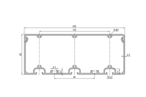 Aluminium Conduit Profile 200×80 mm Cable Duct Extrusion 2.5 mm Wall for Long Production Line Runs
200 x 80 mm aluminium conduit profile duct in 6063-T5 with a 2.5 mm…
