Aluminium Conduit Profile 200×80 mm Cable Duct Extrusion 2.5 mm Wall for Long Production Line Runs
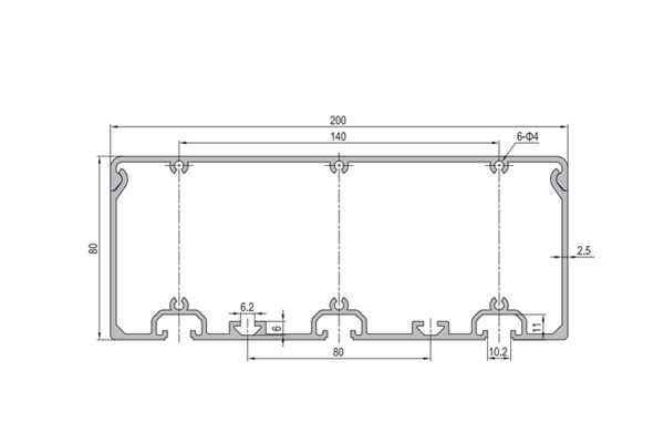
200 x 80 mm aluminium conduit profile duct in 6063-T5 with a 2.5 mm wall for long production line runs. Six Ø4 mm holes, three per wide face, and a 10.2 mm T-slot.
| Material | Aluminium |
|---|---|
| Alloy Grade | 6063-T5 |
| Temper | T5 |
| Section Size | 200 x 80 mm |
| Slot | T-slot 10.2 mm groove, 8 mm mouth, 40 series |
| Length | 6 m stock, cut to drawing to +/-0.5 mm |
| Tolerance | EN 755-9 / GB/T 6892, wall +/-0.15 mm |
| Surface | Mill finish / clear anodised / black anodised |
| MOQ | 300 |
| Lead Time | 20-30 days after deposit for mill finish |
| Loading Port | Shanghai / Ningbo |
| Supply Ability | 400 t per month |
| Payment Terms | T/T 30% deposit + 70% before shipment | L/C at sight |
| Trade Terms | FOB | CIF | EXW |
| Certifications | ISO 9001:2015 | EN 755-9 | RoHS | REACH |
Cable management · Aluminium duct
A 200 x 80 mm aluminium conduit profile is a rectangular duct with a 2.5 mm wall, six Ø4 mm holes, three through each of the two wide faces, and a 10.2 mm T-slot along one narrow face. The internal free area is about 146 cm2, the largest in the aluminium duct range, and the section weighs about 3.4 kg/m. It is extruded in 6063-T5 and supplied cut to length, drilled or machined.
The wall is 2.5 mm rather than the 2 mm used on the smaller sections, and the reason is span. Local bending stiffness in a wall scales with the cube of its thickness, so going from 2 mm to 2.5 mm makes the side wall roughly twice as resistant to bowing under the weight of a cable bundle. That matters because a duct at this size is bought for a run measured in tens of metres, not for a short drop inside a machine, and on a run that long the side walls are the part that gives first.
At this size you are buying a run, not a length
A duct inside a machine is a few lengths long and the section is the whole story. A duct along a production line is a different job. A typical run is 30 to 80 m, and because aluminium duct is supplied in 6 m lengths that is somewhere between five and fourteen joints in a single continuous run.
Every one of those joints is a place where the lid line can step, where the run can drift out of line, and where a fixing can be left loose. The engineering effort on a long run goes into those joints and into the order the work is done, not into choosing the section. The section is settled early; the joints are what the project lives or dies on.
| Run length | 6 m lengths needed | Joints in the run | Main risk |
|---|---|---|---|
| 12 m | 2 | 1 | Joint alignment |
| 30 m | 5 | 4 | Alignment drift along the run |
| 48 m | 8 | 7 | Alignment plus thermal movement |
| 60 m | 10 | 9 | Thermal movement becomes the governing case |
| 80 m | 14 | 13 | Expansion joints are mandatory |
Joining two lengths so the lid line stays straight
The lid runs in the tongue on the narrow face, and that tongue has to be continuous across a joint or the lid catches. Three things decide whether it will be: how the two lengths are butted, whether the splice stiffens the joint, and whether the joint is free to move.
| Joint method | What it does | Effect on the lid line | Use it when |
|---|---|---|---|
| Butt joint, no splice | Lengths simply meet | Steps if the ends are not dead square | Short runs only |
| Internal splice plate | A plate bridges the joint inside the duct | Holds the line if the plate is a close fit | The usual production line joint |
| External coupler | A plate bridges the joint outside the duct | Keeps the line but leaves a step outside | Where the inside must stay clear |
| Overlapping cover strip | One length laps over the next | Continuous but the section changes locally | Where a sliding joint is needed |
| Welded butt | The two lengths are welded | The best line, no step at all | Shop-built runs that can be welded flat |
Alignment: measure from one datum, never chain
On a 60 m run with nine joints, a joint set half a millimetre out of line is not noticeable on its own. Nine of them, each measured from the previous one, put the far end 4.5 mm out, and that is before any cutting error is added. That is the difference between a run that reads as straight and one that visibly wanders.
The fix is to mark every support and every joint position from a single datum at one end of the run, rather than measuring from the last support. Measuring from a datum means each position carries only its own error; chaining means every position carries the sum of all the errors before it.
| Method | Error at the far end of a 60 m run | Comment |
|---|---|---|
| Chained from the previous support, 0.5 mm each | About 4.5 mm over 9 joints | Visible wander |
| Chained with 1 mm per joint | About 9 mm | Clearly out of line |
| Measured from a single datum | The error of that position only | The right method |
| Datum plus a laser or string line | Under 1 mm over the run | Best for long runs |
Thermal movement, and why a 60 m run cannot be pinned at both ends
Aluminium expands by about 23 parts per million per degree Celsius. Over a 60 m run and a 30 degree swing between a cold workshop and a warm production day, that is about 41 mm of movement in the length of the run.
That movement is small enough to be absorbed if the duct is free to slide, and it is not small at all if it is restrained. The section has a cross-sectional area of about 12.6 cm2, and restraining a change of that size in a section of that area develops a force of roughly 60 kN, which is far more than any bracket, bolt or support will hold. The run will either buckle sideways or tear its fixings out.
| Run length | Movement over a 30 degree swing | How to allow for it |
|---|---|---|
| 12 m | About 8 mm | Absorbed by hole clearance in the fixings |
| 30 m | About 21 mm | Slotted fixings at one end of each length |
| 48 m | About 33 mm | One expansion joint about mid-run |
| 60 m | About 41 mm | Expansion joints every 20 to 25 m |
| 80 m | About 55 mm | Expansion joints, plus a check of the fixings |
Installation sequence on site
- Set the datum and mark everything from it Establish one datum line and mark every support and joint position from it before anything is fixed. Do not chain measurements along the run.
- Fit the supports first and check them for line Supports go in before the duct. Fixing brackets to a duct that is already hanging means the duct becomes the straight edge, and it will not be straight.
- Lay out the lengths and mark the joint positions Lay the cut lengths along the run in order and mark where each joint will fall. Move a joint rather than accept one that lands on a support or in a doorway.
- Join the lengths on the ground before lifting Assemble as much of the run as can be handled flat, on the floor, where the joint line can be checked against a straight edge. Joints made at height are never as good.
- Anchor one end and leave the other free Fix the datum end solidly and leave the far end of each section free to move in its slotted fixings. Then check the whole run for line before the lids go on.
- Fit the lids last, working from the datum end Lids go on after the run is fixed and lined up. Working from the datum end means any accumulated step ends up at the far end where it can be trimmed.
This duct or the 160 x 80? Choose the 200 x 80 for runs measured in tens of metres, for large bundles, and where the 2.5 mm wall is needed to stop the side walls bowing between supports. For a shorter run inside a machine, the 160 x 80 carries almost as much and is lighter and cheaper.
Frequently asked questions
How long can a run be before I need expansion joints?
Above about 25 m. Aluminium expands about 23 parts per million per degree, so a 60 m run moves about 41 mm over a 30 degree swing, and restraining that develops roughly 60 kN in this section. Break long runs into sections with expansion joints.
How should two lengths be joined?
An internal splice plate is the usual production line joint: it bridges the joint inside the duct and holds the lid line straight. A welded butt gives the best line of all where the run can be welded flat on the floor before lifting.
How do I keep a long run straight?
Mark every support and joint position from a single datum at one end rather than chaining measurements. Nine joints each measured from the previous one put the far end about 4.5 mm out on a 60 m run, which is visible.
Why is the wall 2.5 mm instead of 2 mm?
Because a run at this length has long unsupported spans, and the side walls bow outward under the cable bundle. Local bending stiffness scales with the cube of the wall thickness, so 2.5 mm is roughly twice as stiff as 2 mm.
Can you supply the run assembled?
Yes. Send the run layout and we will cut to length, drill the Ø4 mm holes to pattern, machine the cable entries, fit the splice plates and supply the assembly in sections ready to lift into place.
Send the run layout and the temperature range on site
Tell us the run length, the temperature swing and what the bundle weighs. We will confirm the section, the support and joint spacing, the expansion allowance, and quote the duct, the splice plates, the lids and FOB pricing.
Request a QuoteRelated Products
 Agricultural Framework Aluminium Profile System 45×45 mm T-Slot for Shelving and Storage Racks
A bolted 45 x 45 mm T-slot aluminium profile framing system for agricultural shelving,…
 Conveyor System Aluminium Profile Extrusion Frame 45×60 mm for Belt and Roller Lines
A bolted conveyor frame in 45 x 60 mm T-slot aluminium profile with 45…
 PG20 60 x 20 mm Eight Slot Aluminium Strut Profile Wide Miniature Rail
60 x 20 mm eight-slot aluminium strut profile with 6.2 mm grooves on a…
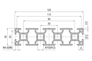 PG30 120 x 30 mm Ten Slot Aluminium Strut Profile Wide Multi Slot Rail
A 120 x 30 mm ten slot PG30 aluminium strut profile wide beam with…
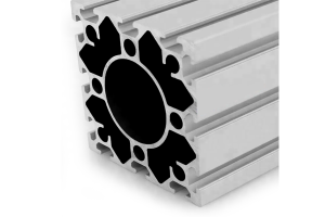 PG40 120×120 mm Twelve Slot Aluminium Strut Profile with 62 mm Centre Bore
A 120 x 120 mm twelve slot PG40 aluminium strut profile with a 62…
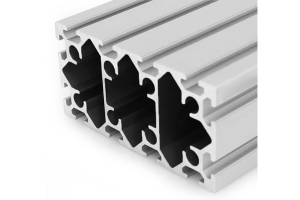 PG40 160×80 mm Twelve Slot Aluminium Strut Profile Heavy Beam for Gantry Frames
A 160 x 80 mm twelve slot PG40 aluminium strut profile heavy beam with…
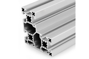 PG40 80×80 mm L-Shape Eight Slot Aluminium Strut Profile Corner Section
An 80 x 80 mm L-shape eight slot PG40 aluminium strut profile corner section…
 PG40 80×80 mm Eight Slot Heavy Aluminium Strut Profile High Load Column
An 80 x 80 mm eight slot heavy PG40 aluminium strut profile with diamond…
