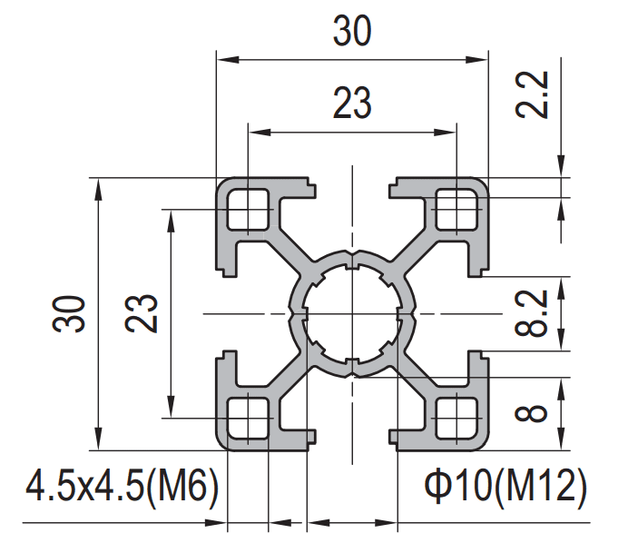
Strut Aluminium Profile 30×30 mm 4-Slot Light T-Slot Extrusion
30 x 30 mm light-wall four-slot T-slot strut aluminium profile in 6063-T5 with M5 grooves on all four faces and a O 10 mm centre bore tapped M12. About 0.95 kg/m for portable, low-cost frames with internal cable routing.
| Material | Aluminium |
|---|---|
| Alloy Grade | 6063-T5 |
| Temper | T5 |
| Section Size | 30 x 30 mm |
| Slot | M5 groove, 4.5 x 4.5 mm, 6 mm mouth, 4 faces |
| Length | 6 m stock, cut to drawing to plus or minus 0.5 mm |
| Tolerance | EN 755-9 / GB/T 6892, wall plus or minus 0.12 mm |
| Surface | Mill finish / clear anodised / black anodised |
| MOQ | 800 |
| Lead Time | 16-26 days after deposit for mill finish |
| Loading Port | Ningbo |
| Supply Ability | 480 t per month |
| Payment Terms | T/T 30% deposit + 70% before shipment | L/C at sight |
| Trade Terms | FOB | CIF | EXW |
| Certifications | ISO 9001:2015 | EN 755-9 | RoHS | REACH |
Light wall · 30 series
A 30 x 30 light four-slot strut profile is a thin-wall T-slot aluminium extrusion with a slot on each of its four faces, an M5 groove of 4.5 x 4.5 mm inside a 6 mm mouth, a O 10 mm centre bore tapped M12, and a wall of about 1.2 to 1.4 mm. It weighs roughly 0.95 kg/m against about 1.30 kg/m for the standard wall of the same envelope. It is the section to specify when the frame has to be portable, cheap in quantity and easy to route cable through, and when the loads are light and short-span.
The trade for that weight is not one thing but four: the section deflects more, the M5 slot will not take the same tightening torque, the centre bore carries fewer usable threads, and the thin lips dent more easily in handling. None of those is a reason to avoid the section; they are the reason it has a boundary. Below about 800 mm between supports and about 200 N of load, the light wall behaves like the standard wall. Past roughly 1 m the difference stops being academic, and the answer is a standard-wall 30 series or a move up to the 40 series, not a heavier bolt.
What a light wall changes
Take the standard 30 x 30 four-slot die and run the walls down from 1.8 mm to about 1.2 to 1.4 mm and three things happen at once. The section gets lighter and cheaper, because material is the largest single cost in an extruded profile. The internal cavities get larger, because the same 30 mm envelope now has thinner walls around a bigger void. And the section gets more flexible, because bending stiffness depends on how far the material sits from the neutral axis, and thin walls move the material closer to the middle.
The three costs of thin aluminium
- Deflection. The light wall has roughly 2.6 cm4 of second moment of area against about 3.6 cm4 for the standard wall, so at the same load and span it moves about 38 per cent further. At short spans that is invisible; at long spans it is the whole story.
- Thread engagement. The wall behind the M5 slot is too thin to tap reliably, so every fixing goes through a T-slot nut rather than a tapped hole in the extrusion. The centre bore is tapped M12, but the thinner boss around it limits usable tap depth to roughly 12 mm against about 16 mm on the standard section, which is a real difference in pull-out strength.
- Clamping force. A slot fixing loads the two lips of the groove. Thinner lips deflect earlier, so the sensible tightening torque for an M5 screw falls from roughly 2.8 Nm to about 2.0 Nm. Above that the lips deform and the nut no longer slides, which is not recoverable.
- Handling damage. A 1.2 mm wall dents. Dropped bundles, over-tightened clamps and careless mitre cuts all leave marks that a standard wall would shrug off, and on an anodised section a dent cannot be dressed out.
| Property | 30 x 30 light wall | 30 x 30 standard wall |
|---|---|---|
| Wall thickness | 1.2 – 1.4 mm | approx. 1.8 mm |
| Weight | approx. 0.95 kg/m | approx. 1.30 kg/m |
| Moment of inertia | approx. 2.6 cm4 | approx. 3.6 cm4 |
| Deflection, 300 N at 800 mm span | approx. 1.75 mm | approx. 1.27 mm |
| Deflection, 300 N at 1200 mm span | approx. 5.9 mm | approx. 4.3 mm |
| Usable tap depth in the centre bore | approx. 12 mm | approx. 16 mm |
| Sensible torque, M5 slot fixing | approx. 2.0 Nm | approx. 2.8 Nm |
| Relative material cost per metre | 100 | approx. 135 |
The quantified boundary
Read the deflection rows in that table as a serviceability check rather than a strength check. At 800 mm, the light wall moves 1.75 mm under 300 N, which is about L/457 and perfectly acceptable for a cover, a bench or a display frame. At 1200 mm the same load gives 5.9 mm, or L/203, and at that point the frame looks springy even though the stress in the aluminium is still low. The section has not become unsafe; it has stopped looking like a structure, which in most projects is the failure that matters.
Working boundary for the light wall: spans under 800 mm, loads under about 200 N, M5 fixings at low torque, and a frame that is carried rather than stood on. Beyond any one of those, step to the standard wall before considering a bigger bolt. For anything a person stands on, or any guard exposed to impact, start at the standard wall and check it.
Specifying a light-wall section
- State the wall on the order Light and standard wall look identical in a 2D layout and are the same envelope on the outside. If the wall is not written on the purchase order, the factory will supply whichever die is running, and the two are not interchangeable on a weight or stiffness calculation.
- Ask for the certified weight per metre The 0.95 kg/m figure is a planning number. Every die has its own wall and its own tolerance, so ask for the certified weight and the second moment of area on the specific die before the design is signed off.
- Decide the torque before the fastener Because the light wall caps tightening torque at roughly 2.0 Nm for M5, choose the joint detail around that limit: a larger number of fixings at lower torque rather than fewer fixings tightened hard. A joint that relies on high torque is a joint that will crush the lips.
- Plan the cable route with the section The extra internal volume is one of the genuine advantages of the light wall. Route the cable through the section from the start and put the exit points in the machining drawing, rather than drilling the frame on site and breaking the anodising.
- Fix the anodising class early On a 1.2 mm wall an anodic layer of 20 microns is a larger fraction of the material than on a standard wall, and it changes how a nut slides in the groove. Specify the class at enquiry wherever a nut has to move freely.
Fixing the light wall
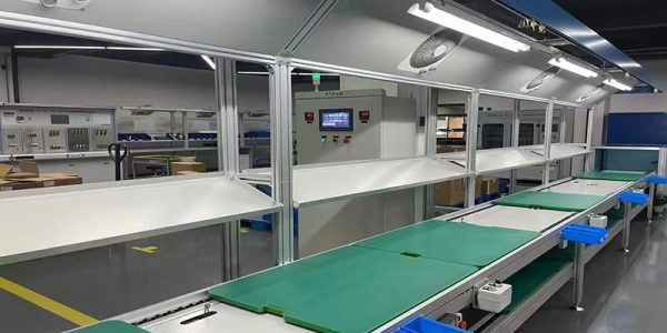
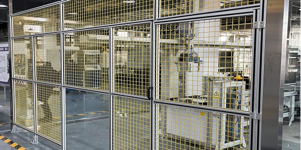
The four M5 grooves take T-slot nuts and nothing else: there is no wall to tap. Corners are made with a light angle bracket or a butt connector inside the section, and because the section is light the bracket often sets the joint capacity rather than the extrusion. Panels are held with panel mounting blocks and the grooves closed with cover strip where the frame is visible.
For a light frame that has to be levelled, a small levelling foot or a base plate is usually enough. Where the frame has to sit flat on a floor, a base plate spreads the load and stops the thin wall from being crushed at the foot.
Frequently asked questions
How much lighter is the light wall than the standard wall?
About 0.95 kg/m against about 1.30 kg/m in the same 30 x 30 envelope, so roughly 27 per cent less material and a similar reduction in price. A 6 m length drops from about 7.8 kg to 5.7 kg.
Can I tap the slot wall of a light 30 x 30 profile?
No. At 1.2 to 1.4 mm there is not enough material for a reliable thread, so every slot fixing goes through a T-slot nut. The centre bore is tapped M12 but usable depth is limited to about 12 mm.
What torque can I use on the M5 slot fixings?
Around 2.0 Nm, against about 2.8 Nm on the standard wall. Above that the groove lips deform and the nut stops sliding, which cannot be corrected afterwards.
At what span should I stop using the light wall?
As a guide, keep the unsupported span under about 800 mm and the load under about 200 N. At 1200 mm the same 300 N load gives about 5.9 mm of deflection, which is visible. Past that, move to the standard wall or a larger section.
Do you supply it cut, machined and anodised?
Yes. We cut to plus or minus 0.5 mm, deburr, tap centre bores and slot ends, drill and counterbore to drawing, and supply mill, clear anodised or black anodised. Send DWG, DXF, STEP or PDF.
Send the load case, get a wall recommendation and a price
Tell us the span, the load and the torque the joint has to take. We will confirm whether the light wall is inside its boundary for your design, or quote the standard wall, then supply cut, tapped, anodised and bagged by assembly with FOB pricing.
Request a QuoteRelated Products
 Strut Aluminium Profile 30×120 mm 3-Slot Wide Beam T-Slot Extrusion
30 x 120 mm three-slot wide-beam T-slot strut aluminium profile in 6063-T5 with three…
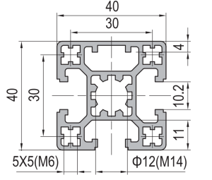 Strut Aluminium Profile 40×40 mm 3-Slot T-Slot Extrusion Closed Face
40 x 40 mm three-slot T-slot strut aluminium profile in 6063-T5 with one solid…
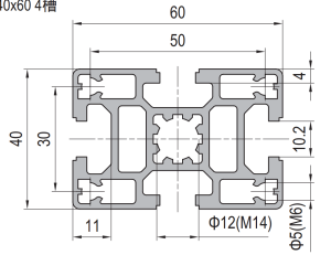 Strut Aluminium Profile 40×60 mm 4-Slot Rectangular T-Slot Extrusion
40 x 60 mm four-slot rectangular T-slot strut aluminium profile in 6063-T5 with M6…
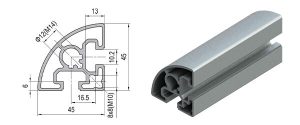 Radius Corner Aluminium Profile 45×45 mm Quarter Round Trim Section
45 x 45 mm quarter-round radius corner aluminium trim section in 6063-T5 with an…
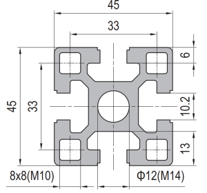 Strut Aluminium Profile 45×45 mm 4-Slot Heavy Duty T-Slot Extrusion
45 x 45 mm heavy duty four-slot T-slot strut aluminium profile in 6063-T5 with…
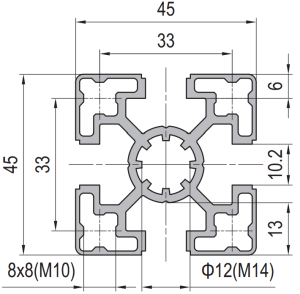 Strut Aluminium Profile 45×45 mm 4-Slot Light T-Slot Extrusion
45 x 45 mm light wall four-slot T-slot strut aluminium profile in 6063-T5 with…
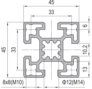 Strut Aluminium Profile 45×45 mm 4-Slot Standard T-Slot Extrusion
45 x 45 mm four-slot standard T-slot strut aluminium profile in 6063-T5 with walls…
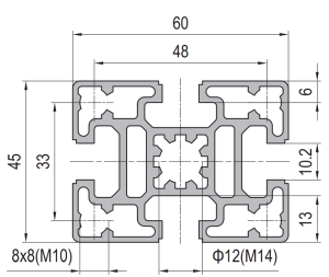 Strut Aluminium Profile 45×60 mm 4-Slot Column T-Slot Extrusion
45 x 60 mm four-slot rectangular T-slot strut aluminium profile in 6063-T5, about 3.3…
