Strut Aluminium Profile 40×60 mm 4-Slot Rectangular T-Slot Extrusion
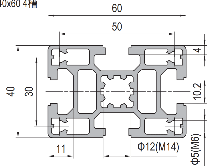
40 x 60 mm four-slot rectangular T-slot strut aluminium profile in 6063-T5 with M6 slots on all four faces and a O 12 mm centre bore tapped M14. A beam section whose stiffness changes by about 85 per cent with orientation, at the same 2.55 kg/m.
| Material | Aluminium |
|---|---|
| Alloy Grade | 6063-T5 |
| Temper | T5 |
| Section Size | 40 x 60 mm |
| Slot | M6 slot, 8 mm mouth, 4 faces, 30 mm module |
| Length | 6 m stock, cut to drawing to plus or minus 0.5 mm |
| Tolerance | EN 755-9 / GB/T 6892, wall plus or minus 0.15 mm |
| Surface | Mill finish / clear anodised / black anodised |
| MOQ | 400 |
| Lead Time | 20-30 days after deposit for mill finish |
| Loading Port | Qingdao / Shanghai |
| Supply Ability | 400 t per month |
| Payment Terms | T/T 30% deposit + 70% before shipment | L/C at sight |
| Trade Terms | FOB | CIF | EXW |
| Certifications | ISO 9001:2015 | EN 755-9 | RoHS | REACH |
Rectangular section · 40 series
A 40 x 60 four-slot strut profile is a rectangular T-slot aluminium extrusion measuring 40 mm by 60 mm with an M6 slot on each of its four faces, a O 12 mm centre bore tapped M14 and a weight of about 2.55 kg/m. It is the member to choose when a frame needs a beam that is stiffer than 40 x 40 without the weight and cost of moving to 60 x 60, and when the beam has to span further than a square section of the same weight allows.
The important property of a rectangular section is that it has a direction. Turned on edge with the 60 mm dimension vertical, the section works at a depth of 60 mm and gives about 24 cm4 of second moment of area. Laid flat with the 40 mm dimension vertical, it works at 40 mm and gives about 13 cm4. It weighs the same either way, so orientation is free stiffness: roughly 85 per cent more, for the cost of deciding which way up to put the beam. At 500 N over a 1500 mm span that is about 2.1 mm of deflection on edge against about 3.9 mm laid flat.
Two directions, two stiffnesses
Bending stiffness depends on how far the material sits from the neutral axis, so for a rectangular section the depth in the direction of the load does most of the work. Doubling the depth multiplies stiffness by roughly eight; doubling the width only doubles it. That is why a 40 x 60 turned the right way outperforms a 60 x 40 turned the wrong way by a wide margin, even though they are the same piece of aluminium.
The practical consequence is that the first decision on a 40 x 60 beam is not the section size, the wall thickness or the alloy. It is which dimension stands up.
| Orientation | Depth against the load | Moment of inertia | Where it belongs |
|---|---|---|---|
| 60 mm vertical (on edge) | 60 mm | approx. 24 cm4 | Cross beams, bench rails, longer spans |
| 40 mm vertical (laid flat) | 40 mm | approx. 13 cm4 | Compact posts, shallow frames, tight gaps |
| 40 x 40 four slot, reference | 40 mm | approx. 9.2 cm4 | General frame member |
| 60 x 60 four slot, reference | 60 mm | approx. 42 cm4 | Column and heavy beam |
Orientation rule of thumb: if the member spans more than about 800 mm and carries anything at all, stand the 60 mm dimension up. Only lay it flat when the design needs a shallow member, or when the 40 mm dimension is the one that has to fit into a gap.
Which way up
Mixing 40 x 60 beams with 40 x 40 columns
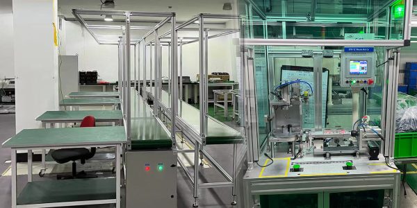
The most common way to use this section is not as a whole frame but as the beams in a frame built from 40 x 40 columns. The reason is economic: 40 x 40 has the largest accessory range of any section and is the cheapest member per metre, so it makes a good column, while the 40 x 60 takes the span. Because both sections sit on the same 30 mm slot module, the T-slot nuts, angle brackets and joining plates interchange without adaptors.
- Design the column in 40 x 40 and check it In a mixed frame the columns are usually the limiting member, because they are the smaller section and they also carry the bending from any horizontal load. Check the column, not just the beam, before reducing it to 40 x 40 to save money.
- Watch the end face geometry A 40 x 60 beam presents a 60 mm tall end face against a 40 mm column face. A plate sized for the beam will overhang the column, so specify the plate to match the column and let the beam slot carry the connection, or use a plate that spans both and accept the overhang deliberately.
- Keep one slot module across the frame Both sections use the 30 mm module, so set the frame out on that module and the beam slots will line up with the column slots. Mixing modules mid-frame is the usual cause of a hole that has to be drilled on site.
- Decide the beam orientation before the cut list The cut list does not change with orientation, but the machining does: which face is drilled, which end is tapped and where the counterbores go all depend on which way up the beam sits. Fix the orientation on the drawing first.
- Plan the finish as one batch Mixed frames are usually visible, and a 40 x 60 beam next to 40 x 40 columns shows any colour difference between anodising batches. Anodise the whole frame order together.
Fixing and finishing
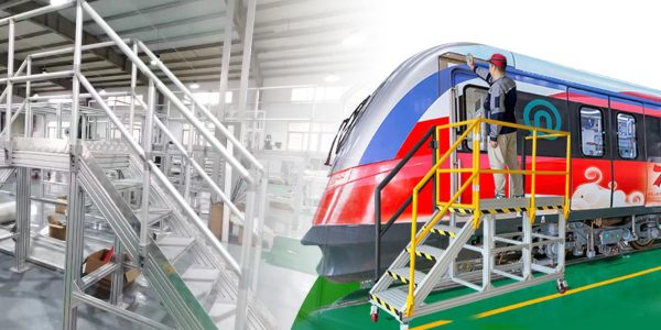
The four M6 slots take the full 40-series accessory range. Corner and tee joints use an angle bracket or a butt connector; a heavily loaded beam-to-column joint is normally made with a joining plate on the beam face plus a through-bolt in the M14 centre bore. Feet are a base plate or a levelling foot on the column, and panels are held with panel mounting elements rather than drilled through the beam.
Where the beam is visible, the slots are closed with cover strip. Where the beam is a structural edge, leave the slots open so the frame can be extended later. Both are supplied mill finish, clear anodised or black anodised, cut to plus or minus 0.5 mm and deburred.
Frequently asked questions
How much stiffer is a 40 x 60 on edge than laid flat?
About 85 per cent. The second moment of area is roughly 24 cm4 with the 60 mm dimension vertical and about 13 cm4 with the 40 mm dimension vertical, at the same 2.55 kg/m. At 500 N over 1500 mm that is about 2.1 mm against about 3.9 mm of deflection.
Can I use 40 x 60 as a column?
You can, but a square section is usually better value for a column because a column needs similar stiffness in both directions. The usual arrangement is 40 x 60 beams on edge with 40 x 40 or 60 x 60 columns.
Do 40 x 60 and 40 x 40 share the same accessories?
Yes. Both sit on the same 30 mm slot module and use the same M6 slot geometry, so T-slot nuts, brackets, joining plates, feet and panel fixings interchange. Only the end face dimensions differ, which affects the plate you choose at a joint.
What is the maximum span for a 40 x 60 beam?
It depends on the load and the deflection you will accept. As a guide, on edge it is comfortable to about 1.8 m for a light load and about 1.2 m for a working load. Send the load and span and we will confirm the deflection rather than quoting a section that looks right.
Can you supply it cut, machined and anodised to a drawing?
Yes. We cut to plus or minus 0.5 mm, deburr, tap the M14 centre bore and slot ends, drill and counterbore to drawing, and supply mill, clear anodised or black anodised. Send DWG, DXF, STEP or PDF with the orientation marked.
Send the span and the load, get an orientation check and a price
Tell us the span, the load and which way up the beam can sit in your layout. We will confirm the deflection on edge and flat, check the columns in a mixed frame, then quote the section, the machining and FOB pricing with the beams cut, deburred and bagged by assembly.
Request a QuoteRelated Products
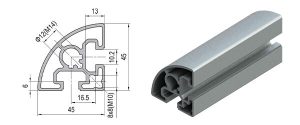 Radius Corner Aluminium Profile 45×45 mm Quarter Round Trim Section
45 x 45 mm quarter-round radius corner aluminium trim section in 6063-T5 with an…
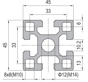 Strut Aluminium Profile 45×45 mm 4-Slot Heavy Duty T-Slot Extrusion
45 x 45 mm heavy duty four-slot T-slot strut aluminium profile in 6063-T5 with…
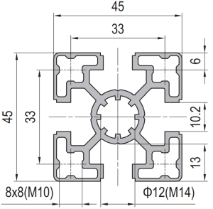 Strut Aluminium Profile 45×45 mm 4-Slot Light T-Slot Extrusion
45 x 45 mm light wall four-slot T-slot strut aluminium profile in 6063-T5 with…
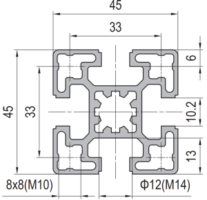 Strut Aluminium Profile 45×45 mm 4-Slot Standard T-Slot Extrusion
45 x 45 mm four-slot standard T-slot strut aluminium profile in 6063-T5 with walls…
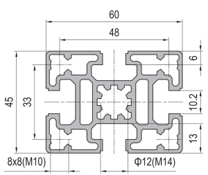 Strut Aluminium Profile 45×60 mm 4-Slot Column T-Slot Extrusion
45 x 60 mm four-slot rectangular T-slot strut aluminium profile in 6063-T5, about 3.3…
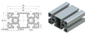 Strut Aluminium Profile 50×100 mm 2-Slot Heavy T-Slot Beam Extrusion
50 x 100 mm heavy two-slot T-slot strut aluminium beam in 6063-T5, about 6.2…
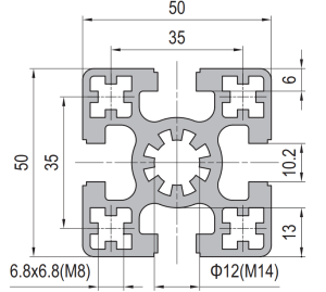 50 x 50 mm Four Slot Aluminium Strut Profile Heavy Frame Cross Member
50 x 50 mm four slot T-slot strut aluminium profile in 6063-T5, about 3.1…
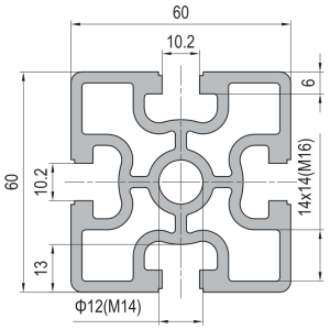 60 x 60 mm Four Slot Aluminium Strut Profile Main Machine Frame Column
60 x 60 mm four-slot T-slot strut aluminium profile in 6063-T5, about 4.3 kg/m…
