60 x 60 mm Four Slot Aluminium Strut Profile Main Machine Frame Column
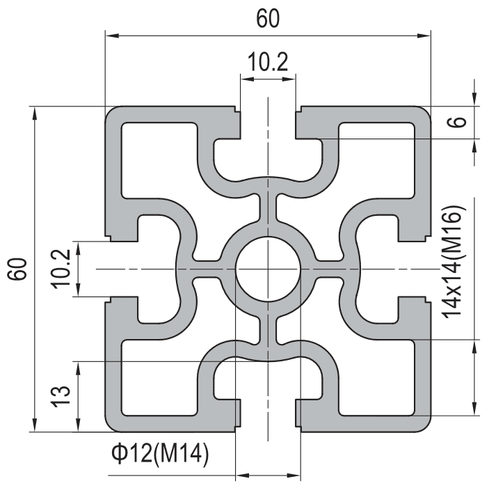
60 x 60 mm four-slot T-slot strut aluminium profile in 6063-T5, about 4.3 kg/m and about 26 cm4. Slots on a 48 mm pitch with a 10.2 mm mouth taking M8 and M10 slot nuts, and a 12 mm centre bore tapped M14.
| Material | Aluminium |
|---|---|
| Alloy Grade | 6063-T5 |
| Temper | T5 |
| Section Size | 60 x 60 mm |
| Slot | 10.2 mm mouth, 14 x 14 mm groove, M8/M10 slot nuts, 4 faces, 48 mm pitch |
| Length | 6 m stock, cut to drawing to +/-0.5 mm |
| Tolerance | EN 755-9 / GB/T 6892, wall +/-0.15 mm |
| Surface | Mill finish / clear anodised / black anodised |
| MOQ | 400 m |
| Lead Time | Typically 20 to 30 days after deposit for mill finish |
| Loading Port | Shanghai, Ningbo, Qingdao |
| Supply Ability | Extrusion, cutting, machining and anodising in house |
| Payment Terms | T/T 30 per cent deposit, balance against copy of bill of lading; L/C at sight for larger orders |
| Trade Terms | FOB, CIF, CFR, EXW |
| Certifications | ISO 9001:2015, EN 755-9, RoHS and REACH declarations |
01What is the 60 x 60 mm four slot profile?
What is it for?
Column duty on large frames. Machine frames and bases, automation and robot cell columns, access platform and walkway frames, guard frame posts, conveyor support columns, heavy benches and test stands, and storage racking uprights. It is the section you move to when a 40 or 45 series member is strong enough but not stiff enough.
How does it compare with the smaller series?
At about 4.3 kg/m and about 26 cm4 it is roughly 2.5 times the weight of a 40 x 40 for about three times the stiffness. That is the trade in one line: you pay more than proportionally in weight and you get more than proportionally in stiffness, because stiffness scales with the square of the depth.
What is unusual about it?
The 14 x 14 mm internal grooves and the size of the section. Together they give you two separate cable routes on one member: one clipped into the grooves and accessible from outside, and one inside the section, protected and out of sight. Smaller series only give you the first.
02Section data
| Item | Value | Note |
|---|---|---|
| Envelope | 60 x 60 mm | square, column duty |
| Slots | 4 | 10.2 mm mouth, 14 x 14 mm groove |
| Slot pitch | 48 mm | the 60 series module |
| Fastener | M8 and M10 | 60 series slot nuts |
| Centre bore | 12 mm, tapped M14 | for end-wise bolting to plates |
| Second moment of area | approx. 26 cm4 | as published |
| Weight | approx. 4.3 kg/m | a 6 m bar is about 26 kg |
| Alloy | 6063-T5 | 6061-T6 on request |
| Standard | EN 755-9 / GB/T 6892 | wall tolerance +/-0.15 mm |
| Length | 6 m stock | cut to drawing to +/-0.5 mm |
The M14 centre bore is the column detail. It is how the member is bolted end-wise to a base plate or a top plate, and it is the reason this section works as a column rather than just as a big frame member.
03Deflection compared: 40, 45 and 60 series at the same span
The reason to step up a series is almost always deflection rather than strength. A frame that is strong enough will still be rejected if a rail sags or a door drops, and deflection falls with the second moment of area, which grows fast with section depth.
The table below is a relative comparison for the same span, the same load and the same support conditions. It is the way to choose a series, not a design calculation.
| Section | Weight | Second moment of area | Relative deflection |
|---|---|---|---|
| 40 x 40 mm | about 1.95 kg/m | roughly 8 to 10 cm4 | 1x, the reference |
| 45 x 45 mm | about 2.7 kg/m | roughly 14 to 17 cm4 | about 0.6x |
| 60 x 60 mm, this section | about 4.3 kg/m | about 26 cm4 | about 0.33x |
| 80 x 80 mm | about 7 kg/m | roughly 60 cm4 and above | about 0.15x |
Read it as: a 60 x 60 member deflects roughly a third as much as a 40 x 40 under the same conditions, for about 2.2 times the weight. Where the consequence of deflection is real — a gantry rail, a long guard rail, a platform edge — that is a good trade.
Where it is not worth it: a short post, a member fully supported along its length, or any place where the extra 60 mm of envelope costs you space you do not have.
Those figures are approximate and are relative comparisons. For an absolute deflection figure, send the span, the load and the support conditions and we will run it against the die drawing.
04Two cable routes on one member
This is the part of the 60 series that gets overlooked on a cut list. A 40 series member has grooves you can clip cable into, and that is the only route you get. A 60 x 60 member has that, and a void inside big enough to run a second route.
The two routes suit different things:
| Route | What goes in it | Advantages | Constraints |
|---|---|---|---|
| In the groove | sensor leads, small harnesses, air line clips | accessible from outside, reworkable at any time | limited by groove size, exposed to damage |
| Inside the section | main power, motor cables, larger bundles | protected, out of sight, no snag points | must be planned before assembly, needs access holes |
The rule that makes it work: power inside, signal in the groove. Keeping the two apart is good practice anyway, and the section gives you the physical separation for free. Plan the access holes with the cut list, because once the frame is assembled the inside is no longer reachable.
Note also that running cable inside a column changes the member: it adds weight, and if the bundle is large it reduces the free area in a way that matters for a tall slender column. On a 2 or 3 m frame post it is never a problem. On a 6 m column it is worth a word with the designer.
05Using it as a column
What a column needs
- Square end facing so it bears flat on a base plate
- The M14 centre bore tapped, with a stated engagement length
- A base plate with a footprint that resists overturning
- Levelling adjustment, usually a foot or a shim stack
- A check on buckling if the column is tall
- Access holes for internal cable, planned before assembly
What a beam needs
- Cut to length and deburred, ends do not have to bear
- No centre bore tapping required
- Ends supported on brackets or on other members
- No levelling: the supports set the level
- A check on deflection, not buckling
- Cable in the grooves, where it stays reachable
The two are different jobs and the order has to say which. A column needs the end facing and the M14 tapping specified; a beam does not, and specifying them on a beam is money spent for nothing.
For tall columns, the buckling check is the one that gets skipped. A 60 x 60 member at 4.3 kg/m is stiff, but a 4 m unsupported column is still slender enough that buckling governs rather than crushing. Plan a mid-height restraint if an upright runs much past 3 m.
06Failure modes to design out
| What goes wrong | Why it happens | Design it out by |
|---|---|---|
| Column does not sit flat on its base | the ends were cut but not faced square | specify square end facing for column duty |
| M14 thread strips at the base | the tapped engagement is short and the bolt was torqued to the steel figure | state the engagement length and torque to the aluminium figure |
| Tall column bows sideways | buckling governs on a slender member and was not checked | add a mid-height restraint tied back to the frame |
| Internal cable becomes unreachable | access holes were not planned before assembly | drill and deburr access holes with the cut list |
| Wrong series hardware arrives | the order said 60 x 60 and not 60 series | quote the accessory list as a 60 series kit |
07What to check before you order
Procurement checklist for the 60 x 60 mm four slot section
- Confirm the series: 60 series is a 10.2 mm mouth on a 48 mm pitch, M8 and M10.
- Confirm whether the member is a column or a beam, because the end preparation is different.
- For columns, confirm square end facing and M14 tapping with the engagement length.
- Confirm whether internal cable is planned, and where the access holes go.
- Confirm the height of any column and whether a mid-height restraint is needed.
- Confirm the accessory list as a 60 series kit: M8 and M10 slot nuts, base plates, cover strips, end caps.
- Confirm the finish and the quantity in metres.
08Terms used on this page
- Column duty
- A member standing upright and carrying compression. It needs square ends and a buckling check.
- End facing
- Machining the cut end square and flat so it bears properly against a plate.
- Buckling
- The sideways failure of a slender member in compression. It is governed by stiffness and length, not strength.
- Centre bore
- The round hole down the middle of the section, here 12 mm and tapped M14 for end-wise bolting.
- Second moment of area
- How the material is distributed about the neutral axis. It governs deflection.
- Access hole
- A hole drilled into the side of a section so cable can be routed through the inside.
09Questions buyers ask
Is it worth stepping up from 45 series?
Where deflection governs, yes. A 60 x 60 deflects roughly a third as much as a 40 x 40 under the same conditions for about 2.2 times the weight. Where the member is short or fully supported, it is not worth it.
What is the weight per metre?
Approximately 4.3 kg/m, so a 6 m stock length is about 26 kg.
Can cable be run inside the section?
Yes, that is one of the advantages of the size. Plan the access holes with the cut list, because the inside is unreachable once the frame is assembled.
How is a column fixed to its base?
The 12 mm centre bore is tapped M14 and the column is bolted end-wise to a base plate. Specify square end facing so it bears flat.
Is 60 series compatible with 40 or 45 series?
No. The pitch is 48 mm against 40 mm and 45 mm, so brackets and hole patterns do not interchange. Use adapter plates for cross-series joints.
How tall can a column be?
Plan a mid-height restraint for an upright much past 3 m. Buckling governs on a slender member long before crushing does.
What we need to quote this section
- The section reference and the series, stated explicitly.
- Whether the member is a column or a beam.
- For columns: square end facing and M14 engagement length.
- The cut list with lengths and any access hole positions.
- The column height, so we can flag whether a restraint is needed.
- The accessory list as a 60 series kit, including base plates.
- The finish and the quantity in metres.
Quotations are broken out into extrusion, cutting, end facing, tapping, finish and hardware, so you can see which step is driving the cost. Browse the full aluminium profile catalogue and the 60 series aluminium profiles range for related sections.
Building a large frame on 60 series columns?
Send the cut list, the column heights and the base plate requirement. We quote extrusion, end facing, tapping, finish and the 60 series hardware as separate lines.
Request a quotationRelated Products
 Strut Aluminium Profile 60×60 mm Heavy Duty T-Slot Extrusion M16 Bore
60 x 60 mm heavy duty four-slot T-slot strut aluminium profile in 6063-T5 with…
 PG15 Strut Aluminium Profile 15×15 mm Light T-Slot Extrusion
PG15 15 x 15 mm single-slot T-slot strut aluminium profile in 6063-T5, about 0.48…
 Aluminium Conduit Profile 40×40 mm Cable Duct T-Slot Enclosure
40 x 40 mm aluminium conduit profile in 6063-T5 with a 32 x 8.2…
 Aluminium Conduit Profile 40×80 mm Large Cable Duct Enclosure
40 x 80 mm aluminium conduit profile in 6063-T5 with a 66 x 11…
 PG20 80×20 mm Ten Slot Aluminium Strut Profile Wide Flat Beam for Cable Tray and Panel Support
80 x 20 mm ten slot PG20 aluminium strut profile in 6063-T5 with a…
 PG20 40×40 mm Eight Slot Aluminium Strut Profile 20 mm Pitch T-Slot Extrusion for Dense Fixtures
40 x 40 mm eight slot PG20 aluminium strut profile in 6063-T5 with two…
 PG30 30×30 mm Two Slot Type A Aluminium Strut Profile Closed Face T-Slot Extrusion
30 x 30 mm Type A two slot PG30 aluminium strut profile in 6063-T5…
 PG30 30×30 mm Two Slot Type B Aluminium Strut Profile Symmetric T-Slot Extrusion for Corner Posts
30 x 30 mm Type B two slot PG30 aluminium strut profile in 6063-T5…
