PG20 40×40 mm Eight Slot Aluminium Strut Profile 20 mm Pitch T-Slot Extrusion for Dense Fixtures
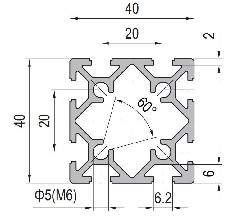
40 x 40 mm eight slot PG20 aluminium strut profile in 6063-T5 with two 6.2 mm grooves per face on a 20 mm pitch and M6 hardware. A dense mounting member for jigs, fixtures and inspection frames.
| Material | Aluminium |
|---|---|
| Alloy Grade | 6063-T5 |
| Temper | T5 |
| Section Size | 40 x 40 mm |
| Slot | 8 x 6.2 mm groove, 6 mm mouth, 20 mm pitch, M6, 2 per face |
| Length | 6 m stock, cut to drawing to +/-0.5 mm |
| Tolerance | EN 755-9 / GB/T 6892, wall +/-0.15 mm |
| Surface | Mill finish / clear anodised / black anodised |
| MOQ | 500 |
| Lead Time | 15-25 days after deposit for mill finish |
| Loading Port | Shanghai / Ningbo |
| Supply Ability | 600 t per month |
| Payment Terms | T/T 30% deposit + 70% before shipment | L/C at sight |
| Trade Terms | FOB | CIF | EXW |
| Certifications | ISO 9001:2015 | EN 755-9 | RoHS | REACH |
Structural framing · PG20 high-density
A 40 x 40 mm eight-slot strut profile is a square aluminium extrusion with the same 40 mm envelope as the familiar four-slot section, but built to the 20 series instead of the 40 series. Its groove is 6.2 mm with a 6 mm mouth, its slot pitch is 20 mm, and it carries eight slots in total — two on each face. The corners take a Ø5 mm hole tapped M6, the web is 2 mm and the flange wall is 6 mm. We extrude it in 6063-T5 and supply it cut to length, drilled, tapped or machined.
Two different systems share the 40 x 40 envelope and they are not interchangeable. The 40 series section has a 10.2 mm groove on a 30 mm pitch and one slot per face; this section has a 6.2 mm groove on a 20 mm pitch and two slots per face. The first is a structural member, the second is a mounting surface. Choosing between them is a question of what the frame is for, and the wrong choice is expensive to discover after the frame is built — the hardware of one system simply does not fit the other.
Two systems, one envelope
The 40 mm square is the most useful size in aluminium framing because it is large enough to be structural and small enough to handle. Both the 40 series and the 20 series use it, and from the outside the two sections look almost the same. The difference is entirely in the groove and the pitch, and it decides what the member can be used for.
A 40 series groove is 10.2 mm wide with an 8 mm mouth and takes M8 hardware. That is a real bolt: it carries load, and one slot per face on a 30 mm pitch is enough because a structural joint only needs one or two fixings. A 20 series groove is 6.2 mm with a 6 mm mouth and takes M6 hardware. It carries less, but it can be repeated — two per face on a 20 mm pitch, which is what turns the member into a mounting surface rather than a beam.
| Property | PG20 40 x 40 eight slot | PG40 40 x 40 four slot |
|---|---|---|
| Slot groove | 6.2 mm, 6 mm mouth | 10.2 mm, 8 mm mouth |
| Fastener | M6 (20 series) | M8 (40 series) |
| Slot pitch | 20 mm | 30 mm |
| Slots per face | 2 | 1 |
| Web wall | 2 mm | 4 mm |
| Corner holes | Ø5 mm, tapped M6 | Ø5 mm, tapped M6 |
| Second moment of area | approx. 5.0 cm4 | approx. 9.2 cm4 |
| Weight | approx. 1.05 kg/m | approx. 1.75 kg/m |
More slots is not automatically better
Doubling the number of grooves costs material, and the material comes out of the web. On this section the web is 2 mm where the 40 series section has 4 mm, which is why the second moment of area is roughly 45 % lower even though the outside dimensions are identical. A frame built from the eight-slot section is a lighter, softer frame than the same frame built from the four-slot section, and it will deflect more over the same span.
That is a fair trade only when the frame’s job is to hold things in position rather than to carry them. Jigs, fixtures, inspection frames, sensor mounting plates, test stands and adjustable shelving all fall into that category: they need many fixing points at fine intervals and they do not need to resist large bending moments. Put the same section under a machine base or a load-bearing beam and it will be the wrong member.
What a 2 mm web means for machining
The thin web is the practical constraint on this section, and it is worth understanding before the drawing is released. Two millimetres of aluminium behind a 6.2 mm groove is enough to hold a nut captive and to resist the pull of a tightened M6 bolt, but it is not enough to take a thread or to survive an over-torqued fastener.
- No direct tapping: a thread cut into a 2 mm web has roughly two threads of engagement, which will strip long before the bolt reaches working load. Every connection goes through a T-slot nut or a machined block.
- Torque limit: specify a torque for M6 fixings, typically 8 to 10 N·m, and hold to it. The groove lips deform before the bolt fails, and a deformed groove stops a nut sliding along the member.
- No self-tapping screws: they split the web rather than cut it. Where a light cover has to be fixed directly, use a slot nut rather than a screw into the extrusion.
- Machining is still fine: cut, drill, counterbore, notch and mitre operations are all normal on this section. It is only the tapped hole in the web that has to be avoided.
Specifying it so the frame assembles first time
- Confirm the system before the section State PG20 or PG40 on the order, not just 40 x 40. The two are not interchangeable and a mixed delivery cannot be assembled without adaptors.
- Give the fixing schedule Because the point of this section is fixing positions, the drawing should show where they are. We can pre-drill and counterbore to that schedule so the assembler is not measuring on site.
- State the torque limit on the drawing A 2 mm web relies on the assembler respecting a torque figure. Put it on the drawing rather than in a note that never reaches the bench.
- Decide the finish with the frame in mind If the frame is visible or is used near food or clean areas, anodise the whole order in one batch to avoid a colour step between deliveries.
Frequently asked questions
Is this the same as a standard 40 x 40 four-slot profile?
No. The outside is 40 x 40 mm on both, but this section is built to the 20 series: a 6.2 mm groove on a 20 mm pitch with two slots per face. A standard 40 series section has a 10.2 mm groove on a 30 mm pitch with one slot per face. The hardware is not interchangeable.
Will 40 series nuts fit the slots?
No. 40 series nuts are sized for a 10.2 mm groove and will not enter a 6.2 mm groove. Use 20 series M6 nuts and hammer-head bolts with this section.
Can I mix this section with 40 series members in one frame?
Only through a machined adaptor plate. Because the grooves differ, a direct connection is not possible. The usual arrangement is a stiff 40 series spine with PG20 rails bolted to it where dense mounting is needed.
How much load can it take?
The section is a mounting member rather than a load-bearing one. As a working guide, keep unsupported spans under about 800 mm for a lightly loaded fixture and under about 500 mm where the frame has to stay straight. Send the load case and we will check it.
Do you supply it cut and drilled to a fixing schedule?
Yes. We cut to +/-0.5 mm, deburr, drill and counterbore to the positions on the drawing, and tap the corner holes. Send DWG, DXF, STEP or PDF and we quote from the drawing rather than from a length list.
Send the fixing schedule, get a quote
Tell us the frame layout and where the fixings fall. We will confirm whether the 20 series dense section or a 40 series section is the right member, then quote cut lengths, drilling and FOB pricing.
Request a QuoteRelated Products
 PG30 30×30 mm Two Slot Type A Aluminium Strut Profile Closed Face T-Slot Extrusion
30 x 30 mm Type A two slot PG30 aluminium strut profile in 6063-T5…
 PG30 30×30 mm Two Slot Type B Aluminium Strut Profile Symmetric T-Slot Extrusion for Corner Posts
30 x 30 mm Type B two slot PG30 aluminium strut profile in 6063-T5…
 PG30 30×30 mm Three Slot Aluminium Strut Profile Light Frame Column
30 x 30 mm aluminium strut profile with three 8.2 mm T-slots and one…
 PG30 30×30 mm R90 Two Slot Aluminium Strut Profile Rounded Corner Rail
30 x 30 mm quarter round aluminium profile with one 8.2 mm T-slot on…
 PG30 60×30 mm Six Slot Aluminium Strut Profile Rectangular T-Slot Extrusion for Cabinet Uprights
60 x 30 mm six slot PG30 rectangular aluminium strut profile in 6063-T5 with…
 PG30 90×30 mm Eight Slot Aluminium Strut Profile Wide Beam T-Slot Extrusion for Door Frames
90 x 30 mm eight slot PG30 wide beam aluminium strut profile in 6063-T5…
 PG30 90 x 15 mm Seven Slot Aluminium Strut Profile Narrow Multi Slot Rail
90 x 15 mm seven-slot aluminium strut profile with 8.2 mm grooves on a…
 PG30 60×60 mm Eight Slot Aluminium Strut Profile Heavy Duty T-Slot Extrusion for Robot Pedestals
60 x 60 mm eight slot PG30 heavy duty aluminium strut profile in 6063-T5…
