PG20 80×20 mm Ten Slot Aluminium Strut Profile Wide Flat Beam for Cable Tray and Panel Support
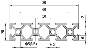
80 x 20 mm ten slot PG20 aluminium strut profile in 6063-T5 with a 6.2 mm groove on a 20 mm pitch and M6 hardware. A wide flat beam for cable tray covers, panel backing rails and enclosure top rails.
| Material | Aluminium |
|---|---|
| Alloy Grade | 6063-T5 |
| Temper | T5 |
| Section Size | 80 x 20 mm |
| Slot | 10 x 6.2 mm groove, 6 mm mouth, 20 mm pitch, M6 |
| Length | 6 m stock, cut to drawing to +/-0.5 mm |
| Tolerance | EN 755-9 / GB/T 6892, wall +/-0.15 mm |
| Surface | Mill finish / clear anodised / black anodised |
| MOQ | 500 |
| Lead Time | 15-25 days after deposit for mill finish |
| Loading Port | Shanghai / Ningbo |
| Supply Ability | 600 t per month |
| Payment Terms | T/T 30% deposit + 70% before shipment | L/C at sight |
| Trade Terms | FOB | CIF | EXW |
| Certifications | ISO 9001:2015 | EN 755-9 | RoHS | REACH |
Structural framing · PG20 flat beam
An 80 x 20 mm ten-slot strut profile is a flat extruded aluminium beam, 80 mm wide and only 20 mm deep, carrying ten T-slots on a 20 mm pitch. The slot groove measures 6.2 mm with a 6 mm mouth, so it takes the standard 20-series M6 hardware: T-slot nuts, hammer-head bolts and slot covers. The corners carry a Ø5 mm hole tapped M6, the web is 2 mm and the flange wall is 6 mm. We extrude it in 6063-T5 and supply it cut to length, drilled, tapped or machined.
The one thing that matters more than any other on this section is which way up it goes. Because the section is four times wider than it is deep, bending stiffness is strongly direction-dependent: the same member is roughly ten times stiffer standing on edge than lying flat. A drawing that shows a 80 x 20 beam without a note on orientation is an incomplete drawing, and the mistake is not one that can be fixed on site — the beam has to come off and be turned, which usually means the whole frame comes apart.
Why a flat beam exists at all
A flat beam is not a weaker version of a square beam. It is the answer to a different problem: a space that is wide but shallow. A cable tray cover, the backing rail behind a control panel, the top rail of a machine enclosure, the frame that carries a light diffuser — all of these are places where depth is fixed by something else and cannot be increased. In those positions a square section either does not fit or wastes material, and the correct move is to take the material you are allowed and spread it as far as possible from the bending axis. That is exactly what an 80 x 20 section does.
The ten slots on a 20 mm pitch are the second half of the idea. Because the section is a mounting surface rather than a structural member, what it has to offer is positions: ten grooves across 80 mm means a fixing point roughly every 20 mm along the whole length of the beam, which lets a cover, a panel or a bracket land wherever the drawing happens to put it rather than at one of two predetermined stations.
On edge or flat: the decision that changes everything
Take the same 80 x 20 member and use it two ways. Standing on edge — the 80 mm dimension vertical, the load acting across it — the material is spread 80 mm either side of the neutral axis and the section is stiff. Lying flat, the material sits only 10 mm from the neutral axis on average and the section is soft. The difference is not marginal; it is about a factor of ten.
The table below uses planning values for the section, simply supported over a 1 m span with a 30 kg uniformly distributed load. They are not a substitute for the certified figures for the die you order, but they show the scale of the effect clearly enough to design against.
| Orientation | Second moment of area | Mid-span deflection (1 m, 30 kg) | Right for |
|---|---|---|---|
| On edge (80 mm vertical) | approx. 21 cm4 | approx. 0.3 mm | Anything that carries load or must stay straight |
| Flat (20 mm vertical) | approx. 2.1 cm4 | approx. 2.7 mm | Surfaces that only hold a cover or a panel in place |
The trap: a flat beam is easy to place the wrong way up because both orientations look plausible on a bench. On a drawing, the orientation has to be fixed by a note, an arrow, or a section view — never left to the person assembling the frame.
Choosing the orientation before anything is cut
- Decide what the member actually does If it carries load, holds a panel square, or has to stay visually straight, it goes on edge. If it only provides fixing positions for a light cover, flat is the efficient answer and uses the shallow depth you have been given.
- Check the depth budget against the orientation On edge the section is 80 mm deep. If the available depth is 25 mm, the decision has already been made for you and the member is flat — in which case expect it to need support roughly every 600 to 800 mm rather than every 1.5 m.
- Fix the joint detail to the orientation An on-edge beam is normally jointed through its 80 mm faces; a flat beam is usually bolted down through the same faces into a substrate. Getting this backwards produces a joint that cannot be reached with a driver.
- Note it on the order, not just the drawing Where a member is supplied pre-drilled, the hole pattern depends on which face is up. State the orientation on the purchase order as well as the drawing, or the holes may be put in the face you intended to keep clean.
Where the 20 series flat beam earns its place
What the 20 series slot will and will not do
The 20 series slot is a 6.2 mm groove with a 6 mm mouth, so it accepts M6 hardware and nothing larger. That is a deliberate limit rather than a shortcoming: the narrower groove is what allows ten of them to fit across 80 mm, and the whole point of this section is mounting density.
- Will do: M6 T-slot nuts and hammer-head bolts, slot covers, light panel brackets, cable clips and gland plates, all placed anywhere along the member.
- Will not do: take an M8 bolt, take a thread cut directly into the 2 mm web, or act as a lifting point. Where a connection has to carry a real tension, use the Ø5 mm corner holes or a through-bolt rather than the slot.
- Watch the web: at 2 mm the web is thin enough that a self-tapping screw or an over-torqued nut will deform the groove. Specify a torque limit with the drawing.
Frequently asked questions
Can I use this section as a structural beam?
Yes, on edge and with the load path checked. On edge the section behaves as a conventional beam of similar depth; laid flat it is a surface member only. Tell us the span and the load and we will confirm which orientation and whether a mid-span support is needed.
Why ten slots rather than two or four?
Because the section is a mounting surface. Ten grooves across 80 mm give a fixing position roughly every 20 mm, so a cover, bracket or device can be placed where the design needs it instead of at one of a few fixed stations.
Does the 20 series slot take 30 series nuts?
No. The 20 series groove is 6.2 mm and the 30 series groove is 8.2 mm, so the hardware is not interchangeable. If you need M8 fixings, the correct move is a 30 series section rather than a larger nut in this groove.
How much does an 80 x 20 ten-slot profile weigh?
Approximately 0.6 kg/m in 6063-T5 as a planning figure. The exact weight depends on the die, so ask for the certified value for the specific die you are ordering, particularly if you are pricing a large frame.
Can you pre-drill the corner holes for me?
Yes. We drill and tap the Ø5 mm corner holes, drill and counterbore for brackets, and machine slots and notches to a drawing. Send DWG, DXF, STEP or PDF with the orientation marked and we will quote from the drawing.
Send the drawing with the orientation marked
Tell us the span, the load and which way up the beam sits. We will confirm the orientation, the support spacing and the wall thickness, then return section weight, machining operations and FOB pricing.
Request a QuoteRelated Products
 PG20 40×40 mm Eight Slot Aluminium Strut Profile 20 mm Pitch T-Slot Extrusion for Dense Fixtures
40 x 40 mm eight slot PG20 aluminium strut profile in 6063-T5 with two…
 PG30 30×30 mm Two Slot Type A Aluminium Strut Profile Closed Face T-Slot Extrusion
30 x 30 mm Type A two slot PG30 aluminium strut profile in 6063-T5…
 PG30 30×30 mm Two Slot Type B Aluminium Strut Profile Symmetric T-Slot Extrusion for Corner Posts
30 x 30 mm Type B two slot PG30 aluminium strut profile in 6063-T5…
 PG30 30×30 mm Three Slot Aluminium Strut Profile Light Frame Column
30 x 30 mm aluminium strut profile with three 8.2 mm T-slots and one…
 PG30 30×30 mm R90 Two Slot Aluminium Strut Profile Rounded Corner Rail
30 x 30 mm quarter round aluminium profile with one 8.2 mm T-slot on…
 PG30 60×30 mm Six Slot Aluminium Strut Profile Rectangular T-Slot Extrusion for Cabinet Uprights
60 x 30 mm six slot PG30 rectangular aluminium strut profile in 6063-T5 with…
 PG30 90×30 mm Eight Slot Aluminium Strut Profile Wide Beam T-Slot Extrusion for Door Frames
90 x 30 mm eight slot PG30 wide beam aluminium strut profile in 6063-T5…
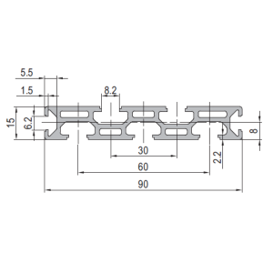 PG30 90 x 15 mm Seven Slot Aluminium Strut Profile Narrow Multi Slot Rail
90 x 15 mm seven-slot aluminium strut profile with 8.2 mm grooves on a…
