Strut Aluminium Profile 50×100 mm 2-Slot Heavy T-Slot Beam Extrusion
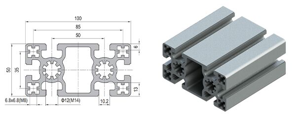
50 x 100 mm heavy two-slot T-slot strut aluminium beam in 6063-T5, about 6.2 kg/m, with two parallel slots along each 100 mm face and a O 12 mm centre bore tapped M14. For large machine frames, robot bases, machine tool guarding and storage racks where the beam's own weight is a design load.
| Material | Aluminium |
|---|---|
| Alloy Grade | 6063-T5 |
| Temper | T5 |
| Section Size | 100 x 50 mm |
| Slot | 6.8 x 6.8 mm groove, M8 slot nuts, two parallel slots on the 100 mm face |
| Length | 6 m stock, cut to drawing to plus or minus 0.5 mm |
| Tolerance | EN 755-9 / GB/T 6892, wall plus or minus 0.15 mm |
| Surface | Mill finish / clear anodised / black anodised |
| MOQ | 200 |
| Lead Time | 25-35 days after deposit for mill finish |
| Loading Port | Tianjin / Qingdao |
| Supply Ability | 260 t per month |
| Payment Terms | T/T 30% deposit + 70% before shipment | L/C at sight |
| Trade Terms | FOB | CIF | EXW |
| Certifications | ISO 9001:2015 | EN 755-9 | RoHS | REACH |
Heavy beam · 50 series
A 50 x 100 two-slot heavy strut profile is an extruded aluminium beam measuring 100 mm wide by 50 mm deep, with two parallel T-slots running along each 100 mm face, a O 12 mm centre bore tapped M14, walls of about 3.0 mm and a weight of about 6.2 kg/m. It is the member for large machine frames, robot bases, machine tool guarding, automated storage racks and heavy gantries: structures where a 40 or 45 mm member is not merely too weak but too narrow to mount anything onto.
The number to hold on to is the weight. At about 6.2 kg/m a 4 m beam weighs nearly 25 kg, and a modest 3 x 2 m frame of four beams and four columns carries roughly 125 kg of aluminium before a single panel or machine is bolted on. That dead load deflects the beam by itself: a 4 m span sags about 6 mm under its own weight with the beam lying 100 mm wide, and about 1.9 mm turned 100 mm vertical. Dead load has to be in the deflection check from the first calculation, not added at the end.
A 100 mm wide beam is bought for its width, not its depth
Most discussions about beams are about depth, because depth is what buys bending stiffness. A 50 x 100 is not that kind of member. With 50 mm of depth and about 50 cm4 about the horizontal axis it is not an efficient way to buy stiffness per kilogram, and a designer who treats it as one will conclude it is expensive.
Its value is in the 100 mm dimension, and it appears in three places: two parallel slot lines on one face instead of one, a 100 mm bearing face that spreads a bolted load, and roughly 150 cm4 about the vertical axis, which is three times its horizontal figure. A wide beam resists sideways forces and mounts wide equipment; that is the job.
The self-weight problem
At about 6.2 kg/m this member is roughly two and a half times the weight of a 45 x 45 standard profile. That is not a detail to be absorbed at the end of the design; it changes the design in three ways at once.
First, the beam deflects under its own weight before any payload is applied. Second, every kilogram of beam has to be carried by the columns, the feet and ultimately the floor, so the column and foot schedule grows with the beam schedule. Third, on a long span the dead load can be a large fraction of the total, which means the payload that the beam can actually carry is smaller than a stiffness calculation based on payload alone would suggest.
| Unsupported span | Self-weight deflection, 100 mm wide | Self-weight deflection, 100 mm vertical |
|---|---|---|
| 2.0 m | approx. 0.4 mm | approx. 0.1 mm |
| 3.0 m | approx. 1.9 mm | approx. 0.6 mm |
| 4.0 m | approx. 6.0 mm | approx. 1.9 mm |
| 5.0 m | approx. 14.7 mm | approx. 4.7 mm |
Put the dead load in first. The figures above are for a simply supported span with no payload at all, on a 6.2 kg/m beam. At 4 m the beam uses about 6 mm of deflection on its own weight before anything is mounted on it. If the design limit is span divided by 500, that is 8 mm at 4 m, and the dead load has already used three quarters of it.
Which equipment actually needs it
The honest test for a 50 x 100 is not the load alone but the combination of load, span and mounting width. A member qualifies when at least two of these three are true: the span is over about 2.5 m, the beam reaction is in the kilonewton range rather than the hundreds of newtons, or the equipment being mounted needs a face wider than 50 mm.
- Large machine frames and bed plates where the base casting or the machine feet need a wide, stiff mounting rail
- Robot bases and robot cell structures where a gantry or a seventh-axis rail has to be bolted along two parallel lines
- Machine tool guarding and enclosures where tall panels are hung from a top rail that also has to resist side loads
- Automated storage and retrieval racks where rail alignment matters more than material cost
- Heavy conveyor gantries and overhead rail supports where the rail has to stay straight across a long clear opening
- Test stands and load frames where the structure is part of the measurement
Specifying it so the design still works
- Start with the dead load, then add the payload Work out the beam weight per metre from the span before anything else, then add the payload to it and check the deflection against span divided by 500. On this member the dead load is not a rounding error.
- Decide the orientation before the layout Lying 100 mm wide the beam gives a broad mounting face and about 50 cm4; turned 100 mm vertical it gives about 150 cm4 but a narrow top face. Fix that choice on the drawing because it changes the bracket, the bolt direction and the panel detail.
- Check the column and the foot as well A frame built from 6.2 kg/m beams has a heavy dead load and it lands on the columns. Size the columns, the base plates and the floor fixings for the frame’s own weight plus the machine, not for the machine alone.
- Detail the joint for an M12 or M14 bolt The O 12 mm centre bore is tapped M14, so the main joint at the beam end can take an M12 through-bolt in grade 8.8 or 10.9, or an M14 thread, at roughly 140 Nm. Slot fixings along the 100 mm face are for the mounted equipment, not for the structural joint.
- Plan the handling and the freight A 6 m length weighs about 37 kg. Cutting to length before shipment reduces freight and handling, and we bag by assembly so a heavy frame is not sorted on site from a pile of similar-looking sections.
Frequently asked questions
When should I use 50 x 100 instead of 60 x 60?
When the mounting face has to be wide or the member has to resist side loads. A 60 x 60 section is more efficient per kilogram for pure bending, but it offers a single 60 mm face and less lateral stiffness.
How much does a 50 x 100 beam weigh per metre?
About 6.2 kg/m, so a 6 m length is roughly 37 kg and a 4 m beam about 25 kg. Treat the beam weight as a design load, because on a long span it consumes a significant part of the deflection allowance.
What bolt does the centre bore take?
The bore is O 12 mm tapped M14, so an M12 through-bolt in grade 8.8 or 10.9 at roughly 140 Nm, or an M14 thread tapped into the end. The two parallel slots on the 100 mm face take M8 slot nuts.
Can I bolt it directly to a machine base?
Yes, and the 100 mm face is usually why the section was chosen. Two parallel slot lines spread the fixing over the full width, which reduces the local pressure on the extrusion compared with a single narrow fixing line.
Do you supply it cut, drilled and anodised to a drawing?
Yes. We cut to plus or minus 0.5 mm, deburr, tap the M14 centre bores, drill and counterbore to drawing, and supply mill finish, clear or black anodised, bagged by assembly.
Send the span and the mounted equipment, we will size the beam
Tell us the clear span, the equipment bolted to the beam and the mounting width it needs. We will check deflection with the beam’s own weight included, confirm whether a 50 x 100 is justified or a deeper section is cheaper, and quote the members cut, tapped and bagged by assembly with FOB pricing.
Request a QuoteRelated Products
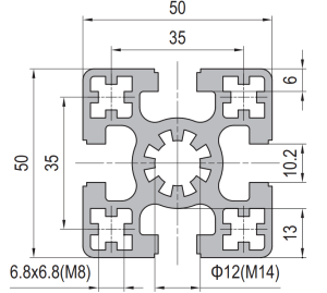 50 x 50 mm Four Slot Aluminium Strut Profile Heavy Frame Cross Member
50 x 50 mm four slot T-slot strut aluminium profile in 6063-T5, about 3.1…
 60 x 60 mm Four Slot Aluminium Strut Profile Main Machine Frame Column
60 x 60 mm four-slot T-slot strut aluminium profile in 6063-T5, about 4.3 kg/m…
 Strut Aluminium Profile 60×60 mm Heavy Duty T-Slot Extrusion M16 Bore
60 x 60 mm heavy duty four-slot T-slot strut aluminium profile in 6063-T5 with…
 PG15 Strut Aluminium Profile 15×15 mm Light T-Slot Extrusion
PG15 15 x 15 mm single-slot T-slot strut aluminium profile in 6063-T5, about 0.48…
 Aluminium Conduit Profile 40×40 mm Cable Duct T-Slot Enclosure
40 x 40 mm aluminium conduit profile in 6063-T5 with a 32 x 8.2…
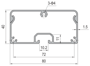 Aluminium Conduit Profile 40×80 mm Large Cable Duct Enclosure
40 x 80 mm aluminium conduit profile in 6063-T5 with a 66 x 11…
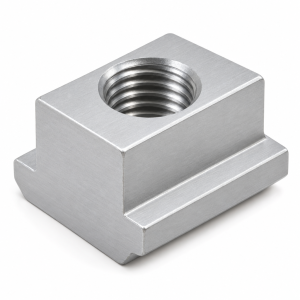 T-Slot Nut 50 Series M10 Hammer Nut for 50×50 Aluminium Extrusion
M10 hammer-head T-slot nut for the 10 mm groove of 50 x 50 mm…
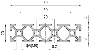 PG20 80×20 mm Ten Slot Aluminium Strut Profile Wide Flat Beam for Cable Tray and Panel Support
80 x 20 mm ten slot PG20 aluminium strut profile in 6063-T5 with a…
