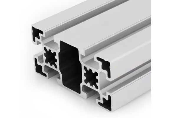
PG40 40 x 40 mm Eight Slot Aluminium Strut Profile High Density Frame
40 x 40 mm eight-slot aluminium strut profile with two T-slots on each face and a Phi12 mm centre bore tapped M14. For frames that need more fixing positions or cable channels than the standard four-slot section.
| Material | Aluminium |
|---|---|
| Alloy Grade | 6063-T5 |
| Temper | T5 |
| Section Size | 40 x 40 mm square, eight slots, two per face |
| Slot | 8 x 10.2 mm groove, 8 mm mouth, two per face, 10 mm between centres, M6 |
| Length | 6 m stock, cut to drawing to +/-0.5 mm |
| Tolerance | EN 755-9 / GB/T 6892, wall +/-0.15 mm |
| Surface | Mill finish / clear anodised / black anodised |
| MOQ | Made to order; small trial lengths available from stock offcuts |
| Lead Time | Typically 2 to 3 weeks for mill finish, about a week longer for anodising |
| Loading Port | Shanghai, Ningbo, Qingdao |
| Supply Ability | Extrusion capacity for standard and custom dies, with in-house cutting, machining and anodising |
| Payment Terms | T/T 30 per cent deposit, balance against copy of bill of lading; L/C at sight for larger orders |
| Trade Terms | FOB, CIF, CFR, EXW |
| Certifications | Mill certificate to EN 10204 3.1 on request, RoHS and REACH declarations |
01What is the 40 x 40 mm eight slot profile?
How is an eight-slot 40 x 40 different from the standard four-slot?
The outer envelope is the same 40 x 40 mm square, and the groove and mouth dimensions are the same 10.2 mm / 8 mm. The difference is that each of the four faces carries two slots instead of one, arranged side by side with about 10 mm between centres. That doubles the number of fixing positions per metre of profile, but it also removes material from the wall between the two slots, dropping the effective wall from roughly 3.0 mm on the four-slot to about 2.0 mm on the eight-slot.
Why would you need eight slots on a 40 x 40?
When one face has to carry both a structural fixing and a cable channel at the same time, or when a panel has to be mounted alongside a sensor rail. On a standard four-slot you would have to choose: the single slot on each face is either holding a bracket or routing a cable, not both. The eight-slot gives you a second lane. It is also used on sliding-door frames where the inner slot holds a track and the outer slot holds the door panel.
Is it stronger or weaker than the four-slot?
Weaker in bending and in per-slot pull-out load. The second slot removes material from the wall, and the section’s second moment of area drops by roughly 12 per cent compared to the standard-wall four-slot. The slot pull-out force also drops: the 2.0 mm wall gives the slot nut about 5 mm of effective engagement instead of 7 mm, so the rated pull-out per M6 nut falls from about 1.5 kN to about 1.0 kN. Section 05 works through the numbers.
02Section data
| Item | Value | Note |
|---|---|---|
| Envelope | 40 x 40 mm | same outer dimensions as the standard four-slot |
| Slots | 8 | two per face, 10.2 mm groove, 8 mm mouth |
| Slot spacing | 10 mm between centres on each face | two slots per face |
| Centre bore | Phi12 mm | tapped M14, same as the four-slot |
| Wall between slots | approx. 2.0 mm | vs 3.0 mm on the standard four-slot |
| Wall on outer faces | approx. 2.5 mm | the land between the slot mouth and the edge |
| Weight | approx. 1.7 kg/m | scaled from the four-slot standard wall at 1.49 kg/m |
| Alloy | 6063-T5 | EN AW-6063 |
| Standard | EN 755-9 / GB/T 6892 | wall tolerance +/-0.15 mm |
| Length | 6 m stock | cut to drawing to +/-0.5 mm |
The weight and wall figures are estimates derived from the published four-slot section in the same 40 series, adjusted for the four additional slots. Treat them as approximate until a certified weighing is required; ask for one on the quotation if the figure feeds into a lifting or transport calculation.
03Where the eight-slot earns its place
The eight-slot is not a replacement for the four-slot. It is a specialist section for frames where one face has to do two jobs at once. Three applications account for most of the volume we ship:
- Cable and pneumatic routing on machine frames: the outer slot holds the bracket, the inner slot carries a cable clip or a pneumatic fitting. No external cable trunk needed.
- Sliding door and access panel tracks: the inner slot takes a nylon track or a roller guide, the outer slot takes the panel fixing. The two are independent, so the door can be removed without releasing the panel.
- Sensor and actuator mounting on automation frames: one slot holds the structural tie, the other holds a sensor bracket or a cylinder cleat. Positioning density doubles without adding a second profile.
In all three, the point is the same: the eight-slot eliminates a second profile or an external accessory by giving each face a second lane. That is where the cost saving is, not in the per-metre price of the extrusion itself.
04How the slots are arranged and what fits them
All eight slots use the same 10.2 mm groove and 8 mm mouth as the standard 40 series, so the full range of M6 slot nuts, hammer head bolts, cover strips and hinges fits without an adapter. The spacing between the two slot centres on each face is about 10 mm, which is enough for two M6 nut bodies to sit side by side without overlapping.
| Slot pair | Faces | Typical use of each lane |
|---|---|---|
| Pair A | front face (two slots) | outer: panel fixing; inner: cable channel |
| Pair B | rear face (two slots) | outer: bracket; inner: pneumatic line |
| Pair C | left face (two slots) | outer: hinge or latch; inner: sensor rail |
| Pair D | right face (two slots) | outer: structural tie; inner: actuator cleat |
The Phi12 mm centre bore is unchanged from the four-slot, so through-bolting with an M14 tie rod works the same way. The bore is coaxial through the section and does not interact with the slots.
05What you lose: bending stiffness and slot pull-out
The eight-slot trades wall material for slot count, and the trade has two measurable consequences.
First, the second moment of area drops. A standard-wall 40 x 40 four-slot has an I of about 5.8 cm4 about each principal axis. Removing the material for four extra slots drops that to about 5.1 cm4, a reduction of roughly 12 per cent. For a 1 m simply supported beam under a centre load, that means about 13 per cent more deflection at the same load.
Second, the slot pull-out force drops. The slot nut grips the groove lips from behind, and the effective engagement length is the wall thickness minus the slot mouth depth. On the four-slot, that is about 7 mm; on the eight-slot, the wall between the two slots is only 2.0 mm, and the effective engagement drops to about 5 mm. The rated pull-out per M6 nut falls from about 1.5 kN to about 1.0 kN.
| Property | Standard 4-slot | 8-slot | Change |
|---|---|---|---|
| I (cm4) | approx. 5.8 | approx. 5.1 | -12 per cent |
| Deflection at 100 N, 1 m span | 0.37 mm | 0.42 mm | +13 per cent |
| Wall between slots (mm) | 3.0 | 2.0 | -33 per cent |
| M6 nut engagement (mm) | 7 | 5 | -29 per cent |
| M6 nut pull-out (kN) | approx. 1.5 | approx. 1.0 | -33 per cent |
| Fixing positions per face per metre | 1 row | 2 rows | +100 per cent |
The four-slot comparison values are taken from the published data for the standard-wall 40 x 40 four-slot section in the same 40 series, available on the 40 series profiles page. The eight-slot values are derived from the same section with four additional slots modelled.
06Choosing between the eight-slot and the standard four-slot
Choose the eight-slot
- A face needs to carry both a fixing and a cable at the same time
- You are building a sliding door frame with a track and a panel on one face
- Sensor and actuator density per face matters more than bending stiffness
- You want to eliminate an external cable trunk from the frame design
- The frame is a perimeter or enclosure, not a load-bearing beam
Choose the standard four-slot
- The member spans between supports and carries bending load
- You need the highest per-slot pull-out for a structural joint
- The frame only needs one fixing per face and simpler is better
- Cost per metre is the primary driver (four-slot is cheaper)
- You want the widest range of heavy-wall variants (the eight-slot only comes in one wall
07Failure modes to design out
| What goes wrong | Why it happens | Design it out by |
|---|---|---|
| Slot nut pulls out under load | the 2.0 mm wall gives less engagement than the four-slot | use the centre bore and an M14 through-bolt for structural tension, not the slots |
| Frame deflects more than expected | the second moment of area is 12 per cent lower than the four-slot | reduce the span or add an intermediate support; do not assume four-slot numbers |
| Cable and bracket interfere in adjacent slots | the 10 mm centre spacing is tight for two M6 fittings side by side | stagger the fittings along the length, or use M5 nuts in the inner lane |
| Wall cracks when tapping the centre bore | the thin wall between slots reduces the material around the bore | specify the bore pre-tapped from the extruder; do not field-tap |
| Cover strips do not seat in adjacent slots | the 10 mm spacing leaves no room for two cover strip legs | use a single wide cover strip that spans both slots, or leave the inner lane open |
08What to check before you order
Procurement checklist for the eight-slot profile
- Confirm the slot assignment: which lane on each face is structural and which is service. Put it on the drawing so the assembler does not mix them up.
- Confirm the cut length and tolerance. The standard cut is +/-0.5 mm; tighter tolerances are available on CNC cut saws.
- Confirm the finish: mill finish for clad frames, clear or black anodised for exposed service. Anodising adds about 10 to 15 micron.
- Confirm whether the centre bore needs to be pre-tapped M14. Field-tapping the thin-wall section is not recommended.
- Confirm the quantity in metres, not pieces. A 6 m bar yields six 950 mm members with 300 mm of offcut.
- If the frame carries bending load, do not assume four-slot deflection numbers. Ask for the second moment of area figure on the quotation.
09Terms used on this page
- Slot density
- The number of T-slots per face of a profile. The standard 40 x 40 has one slot per face (four total); the eight-slot has two per face (eight total).
- Effective engagement
- The length of slot nut contact with the groove lip, measured along the slot axis. It determines the pull-out force per nut.
- Second moment of area
- A measure of how material is distributed about the neutral axis, in cm4. It drives bending deflection, not material strength.
- Through-bolt
- A long bolt that passes through the Phi12 mm centre bore, tying two members together in tension. Independent of the slots.
- Cover strip
- A plastic or aluminium strip that snaps into the slot mouth to seal it against dust or to improve appearance.
- Slot pitch
- The distance between slot centres on a face with more than one slot. On the eight-slot it is about 10 mm.
10Questions buyers ask
Can I use standard 40 series slot nuts and bolts in the eight-slot?
Yes. All eight slots use the same 10.2 mm groove and 8 mm mouth as the standard four-slot, so M6 slot nuts, hammer head bolts, cover strips and hinges all fit without an adapter.
What is the difference between this and the 40 x 40 four-slot?
Same 40 x 40 envelope, same groove size, same centre bore. The eight-slot adds a second slot on each face, doubling fixing positions but reducing the wall from about 3.0 mm to about 2.0 mm. It carries about 12 per cent less bending stiffness and about 33 per cent less slot pull-out per nut.
Is it available in a heavy wall?
No. The eight-slot geometry only leaves room for one wall thickness, about 2.0 mm between slots. If you need a heavier wall, use the standard four-slot, which comes in light, standard and heavy wall variants.
What is it used for?
Frames where one face has to carry both a structural fixing and a cable channel or sensor rail at the same time: machine frames with integrated cable routing, sliding door frames with a track and a panel on one face, and automation frames with dense sensor mounting.
What is the minimum order quantity?
Extrusion is made to order. Small trial lengths are available from stock offcuts; production runs are quoted by the metre or by the tonne depending on finish and quantity. Send the drawing and the annual volume and we will quote both.
Can it be supplied anodised?
Yes. Clear, black, champagne and bronze are standard anodised colours at 10 to 15 micron. Mill finish is available for frames that will be clad or painted by the customer.
What we need to quote this section
- The section drawing or the profile reference, with the eight slots called out.
- The cut length for each member and the number of members.
- The end preparation: square cut, mitre angle, or pre-tapped M14 ends.
- The finish: mill, clear anodised, black anodised, or a specified colour.
- The annual or per-order quantity, in metres or in pieces.
- Any certification requirement: mill certificate to EN 10204 3.1, dimensional report, or first article inspection.
Send those six items and the quotation comes back with the extrusion price, the cutting and machining charge, the finish surcharge and the lead time broken out separately. Browse the full aluminium profile catalogue and the 40 series aluminium profiles range for related sections.
Need this section quoted against your own drawing?
Send the section, the cut list and the finish. We quote extrusion, cutting, machining and anodising as separate lines so the cost of each step is visible.
Request a quotationRelated Products
 PG45 45 x 45 mm Three Slot Aluminium Strut Profile Asymmetric Rail
45 x 45 mm three-slot aluminium strut profile with one solid flat face for…
 PG45 45 x 45 mm Four Slot Aluminium Strut Profile Standard Frame
45 x 45 mm four-slot aluminium strut profile with 10.2 mm grooves, M8 slot…
 PG45 45 x 60 mm Four Slot Aluminium Strut Profile Rectangular Beam
45 x 60 mm four-slot rectangular aluminium strut profile with directional bending stiffness. Strong…
 Aluminium Pipe 28 mm OD Round Tube Profile for Lean Pipe Systems
28 mm OD round aluminium tube for lean pipe systems, conveyor rollers and rotating…
 Aluminium I-Beam Profile 40 x 40 mm Structural H-Section Extrusion
Aluminium I-beam (H-section) 40 x 40 mm in 6063-T5. Concentrates material in the flanges…
 Extruded Aluminium Angle Profile 20 to 100 mm 6061 T6 Equal Leg
Extruded aluminium equal leg angle from 20 x 20 x 3 mm to 100…
 Aluminium Angle Extrusion 40x40x5 mm for Frame Assembly and Bracing
40 x 40 x 5 mm aluminium angle extrusion in 6061-T6 for frame assembly…
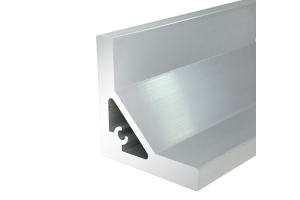 Custom Aluminium Extrusion Profile 20 to 100 mm, 6063-T5
Aluminium extrusion profiles supplied to Canada in 6063-T5 and 6061-T6, mill or anodised, with…
