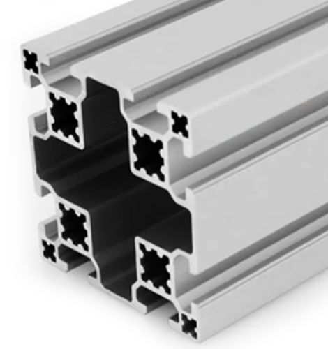
Aluminium I-Beam Profile 40 x 40 mm Structural H-Section Extrusion
Aluminium I-beam (H-section) 40 x 40 mm in 6063-T5. Concentrates material in the flanges for maximum bending stiffness per unit weight. I approx. 15.8 cm4. For structural beam applications.
| Material | Aluminium |
|---|---|
| Alloy Grade | 6063-T5 |
| Temper | T5 |
| Section Size | I-beam (H-section), 40 mm flange x 40 mm web |
| Slot | No T-slots; connections via flange/web through-bolts or external clamps |
| Length | 6 m stock, cut to drawing to +/-0.5 mm |
| Tolerance | EN 755-9 / GB/T 6892, wall +/-0.15 mm |
| Surface | Mill finish / clear anodised / black anodised |
| MOQ | Made to order; small trial lengths available from stock offcuts |
| Lead Time | Typically 2 to 3 weeks for mill finish, about a week longer for anodising; drilled and stiffened beams add time |
| Loading Port | Shanghai, Ningbo, Qingdao |
| Supply Ability | Extrusion capacity for standard and custom I-beam dies, with in-house cutting, drilling and anodising |
| Payment Terms | T/T 30 per cent deposit, balance against copy of bill of lading; L/C at sight for larger orders |
| Trade Terms | FOB, CIF, CFR, EXW |
| Certifications | Mill certificate to EN 10204 3.1 on request, RoHS and REACH declarations, structural calculation on request |
01What is an aluminium I-beam?
What is an I-beam and why is it shaped that way?
An I-beam (also called an H-section) is a structural profile shaped like the letter I: two horizontal flanges (top and bottom) connected by a vertical web. The flanges carry bending tension and compression, and the web carries shear. By concentrating material in the flanges — where it is furthest from the neutral axis — the I-beam gets maximum bending stiffness per unit of material. It is the most efficient shape for a beam that carries a load perpendicular to its axis.
How does it compare to a square tube of the same weight?
A 40 x 40 mm I-beam at 2.2 kg/m has a second moment of area of about 15.8 cm4. A 40 x 40 mm square tube at the same 2.2 kg/m has about 7.7 cm4. The I-beam is about twice as stiff in bending about the strong axis, for the same weight of aluminium. The trade-off is that the I-beam is weaker in torsion and has no T-slots for mounting accessories.
Why not use I-beams for everything then?
Because the I-beam only wins in one direction. About its weak axis (the flange width), the I is only about 2.0 cm4 — eight times less than the strong axis. It has no slots for T-slot nuts, so connections need brackets or through-bolts. And it has low torsional stiffness compared to a closed tube. It is a beam, not a frame member.
02Section data
| Item | Value | Note |
|---|---|---|
| Flange width | 40 mm | the horizontal dimension |
| Web height | 40 mm | the vertical dimension, flange face to face |
| Flange thickness | approx. 3.0 mm | the material in the flanges |
| Web thickness | approx. 2.5 mm | the material connecting the flanges |
| I (strong axis, cm4) | approx. 15.8 | about the horizontal neutral axis |
| I (weak axis, cm4) | approx. 2.0 | about the vertical neutral axis |
| Ratio strong/weak | approx. 7.9 | highly directional |
| Weight | approx. 2.2 kg/m | same as a 40×40 standard-wall square tube |
| Alloy | 6063-T5 | EN AW-6063 |
| Standard | EN 755-9 / GB/T 6892 | wall tolerance +/-0.15 mm |
| Length | 6 m stock | cut to drawing to +/-0.5 mm |
The I and weight figures are derived from the published 40 x 40 mm I-beam section in the same alloy. The strong-axis I is about twice that of a 40 x 40 square tube at the same weight, and about 2.7 times that of a 40 x 40 standard T-slot profile. Treat as approximate until a certified calculation is required.
03Why the I-beam is efficient in bending
Bending stiffness is driven by the second moment of area (I), which measures how far the material is from the neutral axis. The further the material, the higher the I, and the stiffer the beam.
In a square tube, the material is distributed evenly around the perimeter, so some of it is near the neutral axis (where it does little for bending) and some is far from it (where it does a lot). In an I-beam, all the material is either in the flanges (far from the axis) or in the web (carrying shear, near the axis). The flanges do almost all the bending work, and the web does the shear work.
For a 40 mm deep section, the flange material sits at +/-20 mm from the neutral axis. In a square tube, the material near the corners is also at +/-20 mm, but the material near the centre of each face is at +/-10 mm or less. The I-beam puts nothing in the low-efficiency zone.
| Section | Weight (kg/m) | I strong (cm4) | I per kg (cm4 per kg/m) |
|---|---|---|---|
| 40×40 I-beam | 2.2 | 15.8 | 7.2 |
| 40×40 square tube (std wall) | 2.2 | 7.7 | 3.5 |
| 40×40 T-slot profile (std) | 1.49 | 5.8 | 3.9 |
| 40×40 T-slot heavy wall | 2.35 | 7.2 | 3.1 |
The I-beam gives 7.2 cm4 per kg/m, roughly twice the efficiency of any square or slotted section. That is the structural argument for the I-beam: if your application is a beam carrying a bending load, it is the most material-efficient choice.
04What the I-beam cannot do
The I-beam’s efficiency comes at a cost. Three things it does poorly:
| Property | I-beam | Square tube | Why the I-beam is worse |
|---|---|---|---|
| Torsional stiffness | low | high | open section, the web does not close the loop |
| Weak-axis bending | 2.0 cm4 | 7.7 cm4 | flanges are narrow, no material on the sides |
| Slot nut mounting | impossible | yes | no T-slots; connections need brackets or through-bolts |
| Multi-directional load | poor | good | only good for load in the strong-axis direction |
The I-beam is a beam, not a frame member. It is designed to carry a load perpendicular to its axis, in a known direction. If the load direction is unknown or multi-directional, a square tube is a better choice. If the application needs T-slot accessories, use a T-slot profile instead.
05Connections: brackets and through-bolts, not slot nuts
The I-beam has no T-slots, so connections are made with external brackets bolted through the flanges, or through-bolts that pass through drilled holes in the web or flange. Three common connection methods:
- Flange through-bolts: drill through both flanges and bolt a bracket or a plate to the outside. This is the strongest method and carries the highest load.
- Web bolts: drill through the web and bolt a bracket to the side. Weaker than flange bolts, but does not project beyond the flange width.
- Clamp fittings: an external clamp grips the flange from outside. Fast to install, lower load capacity, no drilling needed.
06I-beam vs square tube: choosing the right section
Choose the I-beam
- The member is a beam carrying a known-direction bending load
- Material efficiency matters (lightweight structures, long spans)
- The load is perpendicular to the beam axis, in one direction
- You do not need T-slot accessories along the member
- Torsional stiffness is not required
Choose the square tube or T-slot profile
- The load direction is unknown or multi-directional
- You need T-slot nuts and sliding fittings
- Torsional stiffness matters (twisting frames)
- The member is part of a frame, not a standalone beam
- You want a simpler connection system (slot nuts, no drilling)
07Applications: where the I-beam earns its place
- Long-span beams where deflection is the limiting factor: conveyor support beams, roof purlins, platform walkways.
- Lightweight structures where material efficiency matters: aerospace ground equipment, portable platforms, vehicle frames.
- Solar panel support rails: the I-beam carries the panel weight and wind load efficiently, with brackets bolted to the top flange.
- Structural beams in aluminium frames: where a steel I-beam would be over-specified but a T-slot profile is too weak.
- Material handling guides and supports: overhead conveyor supports, lift guides, sliding track supports.
08Failure modes to design out
| What goes wrong | Why it happens | Design it out by |
|---|---|---|
| Beam buckles sideways (lateral-torsional) | the I-beam has low weak-axis stiffness and low torsional stiffness | add lateral restraint at intervals; or use a wider flange section |
| Web buckles under shear | the 2.5 mm web is thin and can buckle under high shear | add web stiffeners (ribbed or welded plates) at support points |
| Flange bolt pulls through | the 3.0 mm flange is too thin for a countersunk bolt head | use a washer on both sides; or use a flange nut; or specify thicker flange |
| Beam oriented on the weak axis | the I-beam looks similar from both ends and can be rotated 90 degrees | mark the strong axis on the drawing and the beam |
| Joint at the end of the beam fails | the end connection carries the reaction force, which can be high | use a bearing plate or a bolted end cap; do not rely on a single bolt |
09What to check before you order
Procurement checklist for the I-beam
- Confirm the beam orientation: which direction is the load, and which way is the strong axis. Put it on the drawing.
- Confirm the span and the deflection limit: the I is 15.8 cm4; calculate the expected deflection before ordering.
- Confirm the connection method: flange through-bolts, web bolts, or external clamps. Specify hole positions on the drawing.
- Confirm whether web stiffeners are needed at support points.
- Confirm the finish: mill for structural, anodised for corrosion.
- Confirm the alloy: 6063-T5 is standard; 6061-T6 for higher-strength structural applications.
10Terms used on this page
- Flange
- The horizontal top and bottom parts of the I-beam. They carry bending tension and compression.
- Web
- The vertical part of the I-beam connecting the flanges. It carries shear.
- Strong axis
- The direction about which the I-beam has its highest second moment of area (the horizontal axis through the flanges).
- Weak axis
- The direction about which the I-beam has its lowest second moment of area (the vertical axis through the web).
- Lateral-torsional buckling
- A failure mode where the beam twists and moves sideways under load, because the weak-axis stiffness and torsional stiffness are low.
- Second moment of area
- A measure of how material is distributed about the neutral axis, in cm4. Higher means stiffer in bending.
11Questions buyers ask
Can I use T-slot nuts on an I-beam?
No. The I-beam has no T-slots. Connections use through-bolts in the flanges or web, or external clamp fittings.
What is the difference between an I-beam and an H-beam?
They are the same shape. ‘I-beam’ and ‘H-section’ are interchangeable terms. The naming convention varies by region and standard.
Is it as strong as a steel I-beam?
No. Aluminium is about one-third the stiffness of steel. A 40 mm aluminium I-beam replaces a much smaller steel beam, not an equal-size one. The advantage is weight: aluminium is one-third the density.
Can it be anodised?
Yes. Clear and black anodised are standard. For structural applications, mill finish is usually sufficient unless corrosion is a concern.
What alloy is it supplied in?
6063-T5 as standard. 6061-T6 is available for higher-strength structural applications; it has about 50 per cent higher yield strength but a poorer surface finish.
What is the minimum order quantity?
Extrusion is made to order. Small trial lengths from stock; production runs quoted by the metre or by the tonne.
What we need to quote this section
- The section drawing or the I-beam reference (flange width, web height).
- The cut length for each beam and the number of beams.
- The connection method: flange through-bolts, web bolts, or external clamps. Specify hole positions if known.
- The finish: mill, clear anodised, or black anodised.
- The alloy: 6063-T5 standard or 6061-T6 for higher strength.
- The annual or per-order quantity, in metres or in pieces.
Send those six items and the quotation comes back with the extrusion price, the cutting and machining charge, the finish surcharge and the lead time. Browse the full aluminium profile catalogue and the strut profiles range for related sections.
Need this beam quoted against your own drawing?
Send the section, the span, the connection method and the finish. We quote extrusion, cutting, drilling and anodising as separate lines.
Request a quotationRelated Products
 Extruded Aluminium Angle Profile 20 to 100 mm 6061 T6 Equal Leg
Extruded aluminium equal leg angle from 20 x 20 x 3 mm to 100…
 Aluminium Angle Extrusion 40x40x5 mm for Frame Assembly and Bracing
40 x 40 x 5 mm aluminium angle extrusion in 6061-T6 for frame assembly…
 Custom Aluminium Extrusion Profile 20 to 100 mm, 6063-T5
Aluminium extrusion profiles supplied to Canada in 6063-T5 and 6061-T6, mill or anodised, with…
 Aluminium Extrusion for Sale 20 to 100 mm Stock Lengths Cut to Size 6063 T5
Aluminium extrusion for sale in three routes: stock lengths, cut to size or a…
 Aluminium Extruders 600 to 4000 Ton Press Capacity 40 to 160 mm Profile
Aluminium extrusion capacity across 600 to 4000 tonne presses, covering profiles up to about…
 Aluminium Extrusion Manufacturing Factory: 20 to 100 mm Profiles
Aluminium extrusion profiles for Gujarat, India, in 6063-T5 and 6061-T6, with anodising film selected…
 Aluminium Extrusion Manufacturers: 30 to 60 Series, 8 mm Slot
Aluminium extrusion profiles for Delhi NCR, India, in 6063-T5. Strut sections from 30 to…
 Aluminium Extrusion Profile Supply: 15 to 45 Series Kits, 8 mm Slot
Aluminium extrusion profile supply for Ahmedabad in 6063-T5: electrical cabinet frames with a designed…
