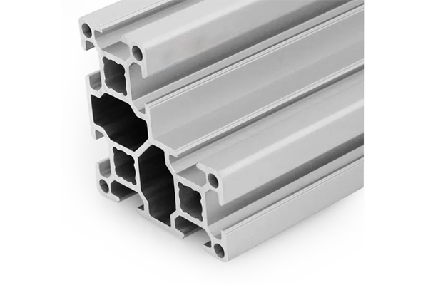
PG30 60×60 mm L-Shape Eight Slot Aluminium Strut Profile Corner Column
A 60 x 60 mm L-shape eight slot PG30 aluminium strut profile corner column with two 30 mm arms at a true 90 degree outside corner, eight 8.2 mm grooves on a 30 mm pitch and a 2.2 mm wall.
| Material | Aluminium |
|---|---|
| Alloy Grade | 6063-T5 |
| Temper | T5 |
| Section Size | 60 x 60 mm L, arms 30 mm |
| Slot | 8 x 8.2 mm groove, 6 mm mouth, 30 mm pitch, on the two 30 mm arms, M6 slot nuts, Phi 4.5 mm corner bores |
| Length | 6 m stock, cut to drawing to +/-0.5 mm |
| Tolerance | EN 755-9 / GB/T 6892, wall +/-0.10 mm |
| Surface | Mill finish / clear anodised / black anodised |
| MOQ | 500 |
| Lead Time | 18-28 days after deposit for mill finish |
| Loading Port | Shanghai / Ningbo |
| Supply Ability | 450 t per month |
| Payment Terms | T/T 30% deposit + 70% before shipment | L/C at sight |
| Trade Terms | FOB | CIF | EXW |
| Certifications | ISO 9001:2015 | EN 755-9 | RoHS | REACH |
Corner section · PG30 60×60 L eight slot
A PG30 60 x 60 mm L-shape eight slot aluminium strut profile is a corner column, not a square tube. Two 30 mm arms meet at a true 90 degrees, so the outside of the corner is one continuous extruded surface with no joint, no bracket and no bolt head showing. Eight 8.2 mm grooves with a 6 mm mouth run on the standard 30 mm pitch, the wall is 2.2 mm, the corner bores are Phi 4.5 for M6, and the section weighs about 2.0 kg/m in 6063-T5.
An L is the section you reach for when the corner itself has to look like a corner, or when a panel has to be held on two faces that meet at 90 degrees without a visible fastener at the joint. But an L is not two square tubes bolted together, and the difference is geometric rather than a matter of strength. The centroid is not where the drawing says it is, and the principal axes are rotated 45 degrees. Both facts change how you drill it, how you load it and when it is simply the wrong choice.
An L is not two square tubes
The obvious way to build an outside corner from strut profile is to cut two square tubes and bolt them together, or to take one square tube and bolt a corner bracket to its face. Both work. Both leave a joint at the corner, and at that joint you can see the bracket, the bolt heads, and the seam where the two sections meet. On a machine frame in a plant nobody minds. On a display frame, a control cabinet, an exhibition stand or a piece of equipment the customer looks at every day, it is the one detail that gives away that the frame was assembled rather than made.
An L removes that joint. The two outer faces of the corner are one continuous extrusion, so the corner is a radius-free true 90 degrees with nothing crossing it. You lose the bracket and two fasteners per corner, and you lose the 8 to 12 mm of length that a bracket needs on each leg, which matters on a small frame where the corner is a noticeable fraction of the member.
What you buy that with is a section that behaves differently from a square tube in three specific ways. They are all consequences of the shape, not of the alloy or the wall thickness, so they cannot be designed out by choosing a heavier profile.
The single most useful thing on this page: on a 60 x 60 L the centroid sits about 5 mm in from the envelope centre on each axis. If you mark holes from the outside faces, or if you centre a bore on the 60 x 60 outline, every hole is 5 mm off in both directions. On a 30 series member that is a quarter of the pitch.
The centroid is not where the drawing says it is
On a square tube the centroid and the geometric centre of the envelope are the same point, and that is why nobody has to think about it. On an L they are not. The material is all on two sides, so the centroid is pulled toward the corner where the two arms meet.
Take the gross outline of the section, treat it as two overlapping rectangles and put the origin at the outside corner. The vertical arm is 30 mm wide by 60 mm tall with its centroid at 15 / 30 mm. The horizontal arm beyond it is 30 mm wide by 30 mm tall with its centroid at 45 / 15 mm. Weighting by area gives a combined centroid at 25 / 25 mm. The envelope centre is at 30 / 30 mm. The offset is 5 mm on each axis, and 7.1 mm measured along the 45 degree diagonal.
| Quantity | Value | How it is obtained |
|---|---|---|
| Envelope | 60 x 60 mm | Catalogue dimension |
| Arm thickness | 30 mm each | Catalogue dimension |
| Envelope geometric centre | 30 / 30 mm from the outside corner | Half the envelope |
| Centroid of the gross outline | 25 / 25 mm from the outside corner | Area-weighted mean of two rectangles |
| Offset per axis | 5.0 mm | 30 mm minus 25 mm |
| Offset along the 45 degree diagonal | 7.1 mm | 5 mm x square root of 2 |
| Gross area | 2,700 mm2 | 1,800 mm2 plus 900 mm2 |
| Gross second moment about the centroid | 74.3 cm4 | Parallel axis on both rectangles |
| Gross product of inertia | -27.0 cm4 | Non-zero, which is the point |
Two caveats before you use those numbers. First, they are computed from the gross outline, so they describe a solid L. The real section is cored out with cavities and ribs, which removes material and lowers the second moment. Treat 74.3 cm4 as an upper bound and the 5 mm offset as the right order of magnitude rather than a drawing value. Second, the offset direction is always toward the outside corner, so it is a fixed feature of the profile, not something you can orient away.
The principal axes are rotated 45 degrees
An equal-armed L has one axis of symmetry: the 45 degree line running through the corner. That line is a principal axis, and the axis perpendicular to it is the other. Neither of them is horizontal or vertical. This is the part that catches people out, because everything about the way the profile is sold suggests a horizontal and vertical frame.
The consequence is unsymmetric bending. Load an L along its horizontal axis and it does not deflect straight down; it deflects down and sideways at the same time, because the product of inertia is not zero. For the gross outline the two principal moments are 101.3 cm4 and 47.3 cm4, a ratio of 2.14. So even measured about its own principal axes, an L is 2.1 times stiffer one way than the other. A square tube has a ratio of 1.0 and a rectangle has a ratio set only by its depth and width, but an L has that ratio as an unavoidable property of the shape.
| Section | Envelope | Arms | Weight | Centroid offset | Gross I about centroid |
|---|---|---|---|---|---|
| PG30 60×60 L (this page) | 60 x 60 mm | 30 mm | approx. 2.0 kg/m | 5.0 mm per axis, 7.1 mm on the diagonal | 74.3 cm4 |
| PG40 80×80 L | 80 x 80 mm | 45 mm | approx. 3.40 kg/m | 5.3 mm per axis, 7.5 mm on the diagonal | 252 cm4 |
| PG45 90×90 L | 90 x 90 mm | 45 mm | approx. 5.60 kg/m | 7.5 mm per axis, 10.6 mm on the diagonal | 376 cm4 |
| PG30 60×60 square, eight slot | 60 x 60 mm | closed | approx. 2.75 kg/m | none, centroid on centre | 108 cm4 |
Same envelope, same series, same eight grooves: the square section is about 31% stiffer in bending than the L, because it puts material in all four walls while the L puts it in two. If the corner is not visible and stiffness is what you need, buy the square section. The L is bought for the corner, and you pay for it in stiffness.
Where an L wins
Where an L loses
- Stiffness. About 31% less bending stiffness than the square section of the same envelope, and about 30% less material, so you cannot simply substitute one for the other in a span calculation.
- Symmetric loading. Because the principal axes are at 45 degrees and the product of inertia is not zero, a load applied along a frame axis produces a skew deflection. If the frame has to stay square, either load it along the 45 degree axis or accept the skew.
- Centreline drilling. Every hole marked from the outside faces is 5 mm out on both axes unless you compensate. The inner corner is also open, so there is no bore at the centre of the section to tap, unlike the square eight slot section.
- Closed boxes. An L occupies about 75% of its envelope, so two of them cannot be nested to close a 60 x 60 box. If you need a closed hollow section, that is what the square profile is for.
- Torsion. The inner corner is open, so the section is not a closed tube. Where a frame has to resist twisting rather than bending, a square or rectangular section does that job with far less material.
The 30 series groove system
| Groove | 8.2 mm internal, 6 mm mouth |
| Slot pitch | 30 mm, the standard 30 series pitch |
| Slots | 8, on the two 30 mm arms |
| Corner bore | Phi 4.5 mm, tapped M6 |
| Centre bore | Phi 10 mm, tapped M12 on the square section |
| Wall | 2.2 mm |
| Alloy and temper | 6063-T5 |
| Weight | approx. 2.0 kg/m |
| Stock length | 6 m, cut to order |
The grooves are the same 8.2 mm groove used across the whole 30 series, so every M6 slot nut, hammer nut, T-bolt, hinge, bracket, foot and end cap in the 30 series range fits this section without an adaptor. That is the practical reason to stay in one series: the hardware is the expensive part of the assembly, and it is interchangeable.
The corner bores are Phi 4.5 mm and take an M6 thread. They are for the small fixings that hold end caps, hinge plates, feet and joining plates, not for structural connections. Structural connections go through the 8.2 mm grooves with M6 slot nuts, and the torque ceiling is set by the wall rather than by the bolt.
Fixing rules for a 2.2 mm wall
- Use the groove for structure. Every load-bearing connection should clamp a slot nut or a T-bolt inside the 8.2 mm groove, where the load is spread over the length of the nut rather than concentrated at a hole.
- Keep torque inside the wall’s limit. The 2.2 mm wall sets the ceiling, not the bolt grade. Around 10 N m is the working limit for an M6 fixing in this groove. Beyond that the slot returns deform and the nut loses its bearing area, which shows up later as a joint that will not stay tight.
- Brace against the skew. Because a load along a frame axis produces a skew deflection, put a diagonal or a gusset in any panel of the frame that has to stay square. A rectangular panel of four L members with bolted corners is a mechanism until something triangulates it.
- Keep drilling off the outside faces. Mark from the centroid, not from the envelope. If you must work from an outside face, allow the 5 mm offset explicitly rather than assuming the centreline is at half the envelope.
- Match the section to the direction of load. Where a member is a beam rather than a corner, the square section is the better buy. Use the L for the corners and the square section for the spans, and the two still share the same hardware.
Cutting, finishing and delivery
The section is supplied in 6 m stock, cut to a cutting list at plus or minus 0.5 mm, with the ends deburred. Corner members are usually mitred on one end and square on the other, or mitred on both ends for a picture frame corner, and mitre accuracy is what decides whether the finished frame closes square. On an L the mitre has to be cut on the outside corner, so tell us which face is the outside face on the drawing.
Finish is mill, clear anodised or black anodised, and colour matching to a RAL or Pantone reference is available on anodised runs. Anodising is done after cutting, so the cut ends are coated and there is no bright aluminium edge to show.
- Send the frame drawing with the outside faces marked and we will return a cutting list and a hardware list.
- Sample lengths of 300 mm are available for fit checks before a full order.
- Mixed orders of L and square sections in the same series ship together and share the same hardware kit.
Send the frame drawing with the outside faces marked
Tell us which face is the outside face and whether the corner is visible. We will return a cutting list, a hardware list and a mitre schedule, and if the corner is hidden we will say plainly that the square section is the better buy.
Request a QuoteRelated Products
 Aluminium Profile Shelf System 40×40 mm T-Slot Uprights for Workshop Racking
A bolted aluminium profile shelf system in 40 x 40 mm T-slot uprights and…
 Aluminium Extrusion Table Frame 20×20 40 mm Workbench Base
20 series aluminium extrusion table frame with 40x40 mm four-slot legs and 40x80 mm…
Aluminium Framing Extrusion Kit 40×40 mm 40 Series Cut List for Machine Frames
A cut-to-length aluminium framing extrusion kit in the 40 series: profile cut to a…
 Aluminium Profile Machine Guard Frame 40 x 40 mm Safety Enclosure
40 x 40 mm T-slot aluminium machine guard frame for safety fences and enclosures,…
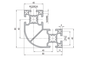 PG40 80×80 mm R90 Six Slot Aluminium Strut Profile Rounded Corner Column
80 x 80 mm L section aluminium corner column with a swept R90 outer…
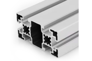 PG40 40 x 40 mm Eight Slot Aluminium Strut Profile High Density Frame
40 x 40 mm eight-slot aluminium strut profile with two T-slots on each face…
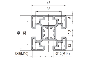 PG45 45 x 45 mm Three Slot Aluminium Strut Profile Asymmetric Rail
45 x 45 mm three-slot aluminium strut profile with one solid flat face for…
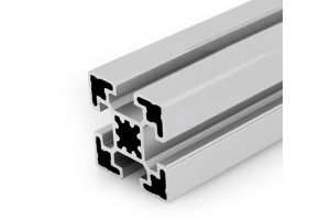 PG45 45 x 45 mm Four Slot Aluminium Strut Profile Standard Frame
45 x 45 mm four-slot aluminium strut profile with 10.2 mm grooves, M8 slot…
