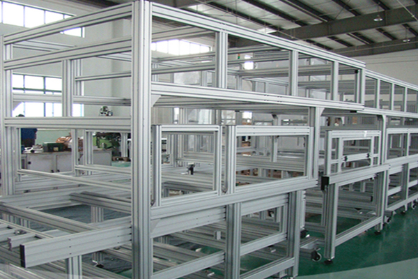
Aluminium Profile Shelf System 40×40 mm T-Slot Uprights for Workshop Racking
A bolted aluminium profile shelf system in 40 x 40 mm T-slot uprights and 40 x 80 mm beams, with shelf levels adjustable in 40 mm steps and all joints made with T-slot hardware.
| Material | Aluminium |
|---|---|
| Alloy Grade | 6063-T5 |
| Temper | T5 |
| Section Size | 40 x 40 mm upright, 40 x 80 mm beam |
| Slot | 8 mm groove, M6 and M8 slot nuts, 40 mm module, 4 faces on the upright and 6 faces on the beam |
| Length | 6 m stock, cut to a cutting list to +/-0.5 mm |
| Tolerance | EN 755-9 / GB/T 6892, wall +/-0.10 mm |
| Surface | Mill finish / clear anodised / black anodised |
| MOQ | 300 |
| Lead Time | 18-28 days after deposit for mill finish |
| Loading Port | Shanghai / Ningbo |
| Supply Ability | 450 t per month |
| Payment Terms | T/T 30% deposit + 70% before shipment | L/C at sight |
| Trade Terms | FOB | CIF | EXW |
| Certifications | ISO 9001:2015 | EN 755-9 | RoHS | REACH |
Shelving system · 40 series bolted rack
A bolted aluminium profile shelf system is a set of 40 x 40 mm four slot T-slot uprights, 40 x 80 mm beams spanning between them, and shelf panels laid on the beams. Everything is bolted through the 8 mm groove with M6 or M8 T-slot hardware, so shelf levels move in 40 mm steps, bays can be added without cutting anything down, and the whole rack can be taken apart and rebuilt somewhere else. A single bay 1,200 mm wide, 600 mm deep and 2,000 mm tall with four levels is about 22 m of profile and around 40 kg of aluminium.
The number that decides whether the rack works is not the size of the upright or the beam. It is the capacity of the weakest element along the load path, and on a light or medium aluminium shelf that element is almost never the beam. A 40 x 80 beam on edge has a second moment of about 62 cm4, which at a 1,200 mm span allows over 500 kg per metre before either deflection or bending is reached. A shelf level rated at 150 kg is therefore limited by something else. This page works down the load path and shows where the real limits sit.
The load path, one link at a time
A shelf level looks like one object and behaves like five. The load starts on the panel, passes into the beams, then through the beam-to-upright connection, down the uprights, into the base plates, and finally into the floor. Each of those five links has a capacity, and the rack is rated at whichever capacity is smallest.
Working the path in order is the only way to size a rack sensibly, because the links differ by a factor of five or more and guessing which one is critical is how racks end up either overbuilt or, more often, quietly underbuilt in a place nobody looked at. The panel is usually the one people forget, and the floor fixing is the one people leave out of the drawing.
| Link | What it carries | What normally sets its capacity |
|---|---|---|
| Shelf panel | The distributed load on the level | Panel span between the two beams, and the panel material |
| Shelf beam | Half the level load at each end | Deflection or bending, whichever is lower at the span used |
| Beam to upright connection | The beam end reaction, in shear and in rotation | Number of bolts per end and whether the beam can rotate |
| Upright | The sum of all levels above, in compression | Buckling over the effective length, not compressive strength |
| Base plate and floor fixing | The whole rack, plus any side load | Anchor type and the overturning check |
The beam is almost never the limiting link
Take the 40 x 80 mm beam on edge, which is the standard choice for a shelf level in the 40 series. Its second moment is about 62 cm4 about the strong axis and about 24 cm4 about the weak axis, both figures taken from the published section data for the standard wall extrusion. Two limits apply. The first is deflection, and for a shelf the sensible limit is span divided by 300, because beyond that the level visibly sags and the panel starts to rock. The second is bending stress, checked at a design stress of 60 MPa, which is a safety factor of about 1.8 on the 110 MPa proof stress of 6063-T5 between 3 and 25 mm wall.
| Span | Deflection limit, L/300 | Bending limit at 60 MPa | Which governs |
|---|---|---|---|
| 0.8 m | approx. 2,210 kg/m | approx. 1,185 kg/m | Bending |
| 1.0 m | approx. 1,130 kg/m | approx. 758 kg/m | Bending |
| 1.2 m | approx. 656 kg/m | approx. 527 kg/m | Bending |
| 1.5 m | approx. 336 kg/m | approx. 337 kg/m | Equal, the crossover |
| 1.8 m | approx. 194 kg/m | approx. 234 kg/m | Deflection |
| 2.0 m | approx. 142 kg/m | approx. 190 kg/m | Deflection |
The crossover at about 1.5 m is worth remembering. Below it the beam fails by bending first, so a heavier wall buys capacity. Above it the beam fails by sagging first, so a heavier wall buys very little and the answer is a shorter bay. If you want to know where to put the next upright, that is the number that tells you.
The striking part is how high both limits are. Even at a 1,200 mm bay, which is a long span for a workshop shelf, the beam allows more than 500 kg per metre of beam, or about 630 kg on the level, before anything is exceeded. A typical light or medium shelf level is rated at 100 to 200 kg. So the beam is carrying a load that is a fraction of what it could take, and the rating is coming from somewhere else.
That is not a reason to use a smaller beam. The beam also has to be stiff enough that the level does not rock when someone leans on one end, and it has to have a slot face deep enough to take the connection. But it is a reason to look at the other four links before you spend money on a heavier beam.
Where the real limits come from
The beam to upright connection
This is the link that most often sets the rating, and the reason is rotation rather than shear. A beam bolted to an upright with a single bolt at each end can rotate about that bolt, so as soon as the load is uneven the level tilts and the load concentrates at one end. The fix is not a bigger bolt; it is two bolts per end, or a bolt-on bracket that gives the beam a bearing face against the upright.
In shear the connection has a large margin. A single M8 T-nut in an 8 mm groove is commonly rated at around 7 kN design pull-out, and the beam end reaction on a 1,200 mm bay carrying 150 kg per level is under 800 N. The failure that actually happens in the field is the beam end working loose and the level going out of level, not a bolt shearing. That is why the drawing matters more than the bolt grade.
The upright
An upright fails by buckling, not by crushing. A 40 x 40 four slot section has a small second moment, and a 2,000 mm free length gives a slenderness ratio well past the point where stability, not strength, governs. Two things follow. First, the upright must be treated as a column with pin ends, because a bolted frame does not develop the fixity a welded frame does. Second, the effective length is the distance between the points that are actually restrained, which is why a tie at mid height is worth more than a heavier section.
Because a bolted corner is effectively a hinge, a free-standing rack is a hinged frame and has very little lateral stiffness of its own. In a workshop that usually does not matter until something pushes it. If the rack is against a wall, tie the uprights back to the wall at the top of each bay. If it stands free, it needs a diagonal in the down-aisle plane and another in the cross-aisle plane, at the ends of the run, in a bay that nobody needs to load from.
The shelf panel
The panel spans between the front and back beam, not across the bay. On a 600 mm deep shelf that is a 600 mm panel span and it is rarely critical. On a 900 mm deep shelf it is 900 mm, and a 25 mm melamine-faced board at that span will sag under a point load in the middle long before the beams notice. Either use a thicker board, put a third beam down the middle, or use a steel deck panel, which is stiffer for the same thickness and does not care about moisture.
The panel also decides how the load reaches the beams. A rigid steel deck spreads a point load along the beam; a soft board does not, and all of it arrives at the nearest bolt. That is one reason two shelves with the same beams and the same stated load can behave differently.
The base and the floor
The last link is the one most often left off the drawing. The uprights sit on base plates, and the base plates have to be anchored, because a rack is a tall thin structure and the load is at the top. Check overturning with the rack empty, since an empty rack is the worst case: the restoring moment comes only from the weight of the frame, while the overturning moment comes from whatever pushes it. An empty 2,000 mm rack on a 600 mm deep base is not difficult to push over.
Levelling feet and base plates are not the same thing. Levelling feet take the frame’s own weight and compensate for an uneven floor. Anchors take the side load. A rack with levelling feet and no anchors looks finished and is not fixed to anything.
Step beam or flat beam
A flat beam is a plain rectangular section laid on its side, and a panel laid on top of it sits on the beam’s upper face. That leaves a lip the height of the beam above the panel, so items cannot slide on and off across the beam. A step beam has a recess formed into the upper profile so the panel sits down inside it and finishes flush with, or just below, the top of the beam.
For a shelf where parts are lifted on and off by hand, the step beam is worth the extra cost, because a flush surface is the difference between sliding a box off the shelf and lifting it over a lip every time. For a shelf that holds static storage and is loaded from the front only, a flat beam with a retained panel is fine and cheaper.
Adjustability, splices and re-use
- Set out the levels on the 40 mm module. Levels move in 40 mm steps because that is the slot module of the 40 series. Set the levels from the floor up, and leave the top level a full module below the top of the upright so there is room for the top tie.
- Never splice an upright inside a beam level. A splice is a joint in compression and it has to be a plate that carries the load across, not a butt joint held by a single bolt. Put splices midway between two levels and stagger them so no two uprights are spliced at the same height.
- Cut the beams, not the uprights. Bay widths are set by the beam lengths, so a change of layout means new beams. Uprights are the expensive part and they can be re-used when the rack is rebuilt, provided the original drawing is kept.
- Keep the hardware with the frame. Bag the T-nuts and bolts by level and label them. A rack that is rebuilt without its own hardware usually ends up with the wrong bolt lengths in the slots, which is how a groove gets stripped.
Ordering a rack as a cut list
We supply shelves as a cut list rather than as a kit of random lengths, because the two things that go wrong on a site-built rack are both length errors. Uprights are cut to the overall height minus the base plate, and beams are cut to the clear bay width minus the two connections. Get either wrong by 5 mm and the rack will not go together square, or the beams will not reach the slots.
Send the bay layout, the level heights and the load per level and we will return a cut list, a hardware list and an assembly drawing. Profile is cut to plus or minus 0.5 mm, deburred and bagged by level, so the rack is assembled rather than made on site. If you already have a frame and only need to add levels, send the section reference and we will match the existing hardware.
- Mixed wall thicknesses are available from the same die family, so a heavy bottom level and light upper levels can share one upright section and one hardware kit.
- Mill, clear anodised and black anodised finishes are all stocked; anodised is worth it in a damp workshop and for anything that gets wiped down.
- Sample lengths are available for a fit check before a full rack is ordered.
Send the bay layout and the load per level
Tell us the bay width, the level heights, the depth and what each level has to hold. We will come back with a cutting list, a hardware list and an assembly drawing, and we will name the link that actually sets the rating.
Request a QuoteRelated Products
 Aluminium Extrusion Table Frame 20×20 40 mm Workbench Base
20 series aluminium extrusion table frame with 40x40 mm four-slot legs and 40x80 mm…
 Aluminium Framing Extrusion Kit 40×40 mm 40 Series Cut List for Machine Frames
A cut-to-length aluminium framing extrusion kit in the 40 series: profile cut to a…
 Aluminium Profile Machine Guard Frame 40 x 40 mm Safety Enclosure
40 x 40 mm T-slot aluminium machine guard frame for safety fences and enclosures,…
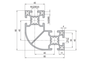 PG40 80×80 mm R90 Six Slot Aluminium Strut Profile Rounded Corner Column
80 x 80 mm L section aluminium corner column with a swept R90 outer…
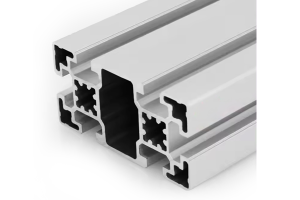 PG40 40 x 40 mm Eight Slot Aluminium Strut Profile High Density Frame
40 x 40 mm eight-slot aluminium strut profile with two T-slots on each face…
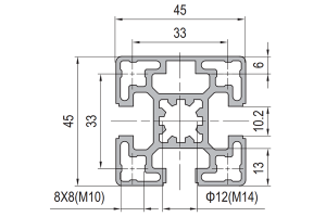 PG45 45 x 45 mm Three Slot Aluminium Strut Profile Asymmetric Rail
45 x 45 mm three-slot aluminium strut profile with one solid flat face for…
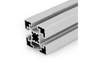 PG45 45 x 45 mm Four Slot Aluminium Strut Profile Standard Frame
45 x 45 mm four-slot aluminium strut profile with 10.2 mm grooves, M8 slot…
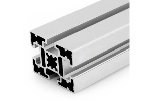 PG45 45 x 60 mm Four Slot Aluminium Strut Profile Rectangular Beam
45 x 60 mm four-slot rectangular aluminium strut profile with directional bending stiffness. Strong…
