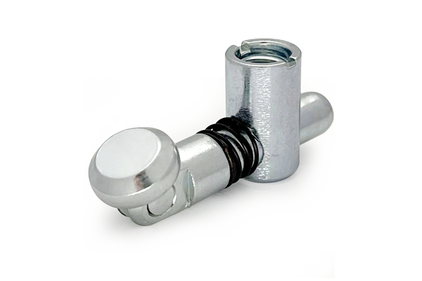
Oblique Connector Model C Angled Joint for 40 mm Aluminium Profiles
Oblique connector Model C for adjustable-angle joints on aluminium T-slot profiles. Internal tie rod, no panel face. Angle range 30 to 150 degrees. For 20, 30, 40 and 45 series.
| Material | Zinc alloy housing / steel tie rod |
|---|---|
| Alloy Grade | Zamak zinc alloy / carbon steel |
| Temper | custom |
| Section Size | Fits 20 / 30 / 40 / 45 mm series profiles |
| Slot | Does not interact with slots; fits the centre bore |
| Length | Housing length varies by series; see data sheet |
| Tolerance | Housing to bore: H8/h7 sliding fit; angle set to +/-1 degree |
| Surface | Zinc plated / black zinc / nickel |
| MOQ | Stocked item; minimum 50 pieces per series |
| Lead Time | Typically 1 to 2 weeks for stocked series and finishes |
| Loading Port | Shanghai, Ningbo, Qingdao |
| Supply Ability | Die-cast and machined in-house; up to 100,000 pieces per month across all series |
| Payment Terms | T/T 30 per cent deposit, balance against copy of bill of lading; L/C at sight for larger orders |
| Trade Terms | FOB, CIF, CFR, EXW |
| Certifications | RoHS declaration on request |
01What is an Oblique Connector Model C?
What does ‘oblique’ mean in this context?
It means the joint is at an angle that is neither 90 degrees (right angle) nor 45 degrees (mitre). The Oblique Model C is a connector that joins two profiles at an adjustable angle, typically between 30 and 150 degrees. The angle is set during assembly and locked by the tie rod.
Why would you need an angled joint?
Not all frames are rectangular. Ramps, inclined conveyors, roof structures, trapezoidal frames, A-frame stands and hexagonal bases all need joints at angles other than 90 degrees. Without an oblique connector, you would have to mitre-cut the profile ends at the exact angle and use an external bracket — slow, expensive and less rigid.
How is it different from the Model P oblique?
The Model C has no panel mounting surface. It is a pure structural connector: two profile ends, one tie rod, one housing, and the angle is set by the housing geometry. The Model P adds a panel mounting face on one side of the joint, for applications that need to hang a panel at the same angle as the joint.
02How it works
The connector has the same three parts as the miter connector: a central housing (zinc alloy) that sits in the corner, a tie rod (steel) that pulls the two profiles together, and a threaded insert in the second profile. The difference is in the housing: instead of a fixed 90-degree pocket, the oblique housing has a pivot that lets the angle be set before the tie rod is tightened.
To assemble: slide the housing into the bore of the first profile, insert the threaded insert into the second profile, set the angle, and tighten the tie rod. The rod locks the housing at the set angle and pulls the two profiles together.
| Part | Material | Function |
|---|---|---|
| Central housing (pivoting) | Zinc alloy (Zamak) | locates the corner, sets the angle |
| Tie rod | Steel, zinc plated | locks the angle and pulls profiles together |
| Threaded insert | Steel, zinc plated | receives the tie rod in the second profile |
| Angle lock screw (some models) | Steel | locks the pivot before tie rod torque |
03Angle range and setting
The typical angle range is 30 to 150 degrees, measured between the two profile axes. At 90 degrees the connector behaves like a miter Model C. At 45 degrees it behaves like a miter Model P. The useful range is outside those two points — the angles in between that no fixed connector covers.
| Angle | Application | Joint behaviour |
|---|---|---|
| 30 degrees | steep ramp, steep roof | high shear on the housing |
| 45 degrees | same as miter Model P | standard mitre geometry |
| 60 degrees | gentle ramp, A-frame | moderate shear |
| 90 degrees | same as miter Model C | right-angle corner |
| 120 degrees | shallow kink, shallow roof | low shear, high tension |
| 150 degrees | nearly straight, slight bend | primarily tension |
The angle is set by eye or with a protractor during assembly. For precision applications, specify the angle on the drawing and use a digital protractor to set it before tightening. Once the tie rod is torqued, the angle is locked and cannot be adjusted without loosening the rod.
04Clamp force vs angle: what happens at shallow angles
The tie rod pulls the two profiles together in tension. At 90 degrees, the tension is perpendicular to both profile axes, and the joint is balanced. As the angle moves away from 90 degrees, the tension develops a component parallel to one profile axis, which creates shear at the housing. The further from 90 degrees, the more shear and the less effective tension.
For a 40 series joint with the standard M14 tie rod torqued to 25 Nm:
| Angle | Effective tension | Shear on housing | Bending capacity |
|---|---|---|---|
| 90 degrees | 8 kN | 0 kN | 50 Nm |
| 60 degrees | 7 kN | 4 kN | 35 Nm |
| 45 degrees | 5.6 kN | 5.6 kN | 25 Nm |
| 30 degrees | 4 kN | 7 kN | 15 Nm |
| 120 degrees | 7 kN | 4 kN | 35 Nm |
| 150 degrees | 4 kN | 7 kN | 15 Nm |
The table shows why very shallow or very steep angles are weaker: at 30 degrees, the joint carries 4 kN of effective tension (half of the 90-degree value) and 7 kN of shear on the housing. For angles outside the 45 to 120 degree range, consider an additional external bracket or a larger series.
05Model C vs Model P oblique: what the panel face adds
Choose Model C oblique (no panel face)
- The joint is purely structural — no panel needed at the angle
- You want simpler assembly (fewer parts, no panel alignment)
- Cost matters — the C is cheaper than the P
- The frame has panels mounted elsewhere, not at the joint
- The angle is in the 45 to 120 degree range where the C is strongest
Choose Model P oblique (with panel face)
- You need to mount a panel at the same angle as the joint
- The panel is structural — it carries shear that the tie rod alone cannot
- You want a finished face at the angled corner
- The angle is outside 45 to 120 degrees and needs the panel for stiffness
- The frame is a clad enclosure where the panel is the visible surface
06Applications: where angled joints are needed
- Ramps and inclined conveyors: the frame slopes at 15 to 30 degrees, and the transition from horizontal to slope needs an angled joint.
- Roof and canopy structures: a peaked roof has joints at 60 to 120 degrees at the ridge and eaves.
- A-frame stands and easels: two legs splay at 60 to 75 degrees, joined at the apex.
- Trapezoidal and hexagonal frames: any frame with non-rectangular geometry needs at least one angled joint.
- Machine frames with angled members: some machine layouts require a member at a non-standard angle for access, clearance or ergonomics.
07Failure modes to design out
| What goes wrong | Why it happens | Design it out by |
|---|---|---|
| Angle drifts after assembly | the tie rod was not tightened enough, or the pivot was not locked | use a torque wrench; tighten the angle lock screw before the tie rod |
| Joint fails at shallow angle | at 30 or 150 degrees the shear on the housing exceeds its capacity | add an external bracket; or move to a larger series; or stay within 45-120 |
| Housing rotates in the bore | no angle lock screw, or the set screw is loose | fit the angle lock screw; tighten before the tie rod |
| Profile end is not square | the cut was at an angle, not square | the connector expects a square cut; check the cut squareness |
| Angle is set incorrectly | set by eye without a protractor | use a digital protractor; specify the angle on the drawing and verify |
08What to check before you order
Procurement checklist for the Oblique Model C
- Confirm the series: 20, 30, 40 or 45. The connector is sized to the profile centre bore.
- Confirm the angle or range of angles the joint needs to cover. If it is a fixed angle, state it on the drawing. If it is adjustable, state the range.
- Confirm whether the angle lock screw is needed (recommended for all angled joints).
- Confirm the cut preparation: square cut on both profile ends, +/-0.5 mm on length.
- If the angle is outside 45 to 120 degrees, add an external bracket or consider a larger series.
- Confirm the finish: zinc plated standard, black or nickel available.
09Terms used on this page
- Oblique
- At an angle that is neither 90 degrees (right) nor 45 degrees (mitre). The oblique connector covers any angle in between.
- Adjustable angle
- The joint angle is set during assembly, not fixed by the die. It is locked by the tie rod.
- Angle lock screw
- A set screw that locks the pivot in the housing before the tie rod is tightened. Prevents angle drift.
- Shear on housing
- The force parallel to the profile axis that the housing must resist. Higher at angles far from 90 degrees.
- Effective tension
- The component of the tie rod force that is perpendicular to both profiles. Decreases at angles far from 90.
- Pivot
- The mechanism in the housing that allows the angle to be set before locking.
10Questions buyers ask
What angle range does the Oblique Model C cover?
Typically 30 to 150 degrees, measured between the two profile axes. At 90 degrees it behaves like the miter Model C; at 45 it behaves like the miter Model P. The useful range is the angles in between.
Do I need to cut the profile ends at an angle?
No. Both ends are cut square (90 degrees). The angle is set by the connector housing, not by the cut.
Can I adjust the angle after assembly?
Only by loosening the tie rod, adjusting the angle, and re-tightening. Once torqued, the angle is locked. For frequent adjustment, use a hinged joint instead.
How is it different from the Oblique Model P?
The Model C has no panel mounting surface — it is purely structural. The Model P adds a panel face on one side of the joint for hanging a panel at the same angle.
Is it as strong as a 90-degree miter connector?
At 90 degrees, yes. At other angles, the effective tension decreases and shear on the housing increases. Below 45 degrees or above 120 degrees, add an external bracket or use a larger series.
What is the minimum order quantity?
Stocked item; minimum 50 pieces per series. Production runs quoted per piece.
What we need to quote this connector
- The series (20 / 30 / 40 / 45) and the profile bore diameter.
- The angle or range of angles the joint needs to cover.
- The number of joints (one connector per angled corner).
- Whether the angle lock screw is needed.
- The finish: zinc plated, black zinc, or nickel.
- The annual or per-order quantity.
Send those six items and the quotation comes back with the connector price, the finish surcharge and the lead time. Browse the connecting elements and other connecting elements ranges.
Need angled connectors quoted for your frame?
Send the series, the angles and the joint count. We quote the connectors and any matching cut preparation as separate lines.
Request a quotationRelated Products
 Oblique Connector Model P Angled Joint with Panel Face for 40 mm Aluminium Profiles
Oblique connector Model P with panel mounting face for angled joints on aluminium T-slot…
 Aluminium Angle Extrusion 40x40x5 mm for Frame Assembly and Bracing
40 x 40 x 5 mm aluminium angle extrusion in 6061-T6 for frame assembly…
 Aluminium Extrusion Profile Supply: 15 to 45 Series Kits, 8 mm Slot
Aluminium extrusion profile supply for Ahmedabad in 6063-T5: electrical cabinet frames with a designed…
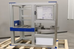 Aluminium Profile Hinge 40 Series 180 Degree for 8 mm Slot Guard Doors
180 degree hinge for 40 series aluminium profile guard doors. Two leaves clamp into…
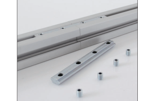 Linear Bar Connector with Top Thread
Hidden linear bar connector that joins two profiles end to end from inside the…
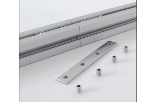 Linear Bar Connector 8/10 with Top Thread
Hidden bar connector made in one length that serves both the 8 mm and…
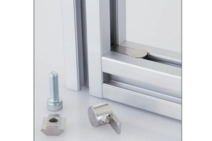 Butt Connector
Connector that joins two profiles end to end in a straight line, transmitting bending…
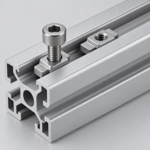 T-Nut for 10 mm Aluminium Profiles M4 M5 M6 M8 M10
Full range of T-slot nuts from M4 to M10 for 15 to 60 series…
