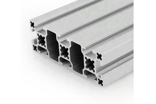
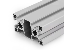
PG40 120×40 mm Eight Slot Aluminium Strut Profile Standard Beam for Table Frames
A 120 x 40 mm eight slot PG40 aluminium strut profile standard beam with three slots on the 120 mm face. For table frames, machine cross beams and rail support beams.
| Material | Aluminium |
|---|---|
| Alloy Grade | 6063-T5 |
| Temper | T5 |
| Section Size | 120 x 40 mm |
| Slot | 8 x 10.2 mm groove, 8 mm mouth, 40 mm pitch, outer pair 80 mm apart, M8 |
| Length | 6 m stock, cut to drawing to +/-0.5 mm |
| Tolerance | EN 755-9 / GB/T 6892, wall +/-0.15 mm |
| Surface | Mill finish / clear anodised / black anodised |
| MOQ | 200 |
| Lead Time | 20-30 days after deposit for mill finish |
| Loading Port | Shanghai / Ningbo |
| Supply Ability | 300 t per month |
| Payment Terms | T/T 30% deposit + 70% before shipment | L/C at sight |
| Trade Terms | FOB | CIF | EXW |
| Certifications | ISO 9001:2015 | EN 755-9 | RoHS | REACH |
Structural framing · PG40 standard beam
A PG40 120 x 40 mm eight slot aluminium strut profile is a wide beam with a 40 mm slot pitch, a 10.2 mm groove and an 8 mm slot mouth, taking 40 series M8 hardware. The 120 mm face carries three slots at 40 mm centres with the outer pair 80 mm apart, the corner holes are 5 x 5 mm tapped M6 and the Ø12 mm bore is tapped M14. The flange is 4 mm and the web 11 mm, and the section weighs about 4.6 kg/m. It is supplied in 6063-T5, cut and machined to order.
The reason to pick a 120 x 40 mm section over a 40 x 120 mm one, or over a plain 80 x 40 mm beam, is the number of separate mounting lines it puts on one face. Three slots at 40 mm centres means three functions can share a single member without any of them competing for space — a rail on one outer slot, an accessory run on the centre slot and a cable route on the other outer slot. Working out which function goes on which slot before you drill anything is the whole design of a table frame.
Three mounting lines on one face
The 120 mm face carries three slots: one central and two outer, with the outer pair 80 mm apart and every slot 40 mm from its neighbour. That geometry is worth using deliberately rather than treating the three slots as interchangeable, because they are not — the outer pair is where the load path wants to be, and the centre is where the middle of the beam is.
| Slot on the 120 mm face | Position | What it is good for |
|---|---|---|
| Outer slot, near edge | 40 mm from the centre slot | Linear rails, guideways and anything that sets a datum |
| Centre slot | On the beam centreline | Accessory brackets, sensor mounts and adjustable items |
| Outer slot, far edge | 40 mm from the centre slot | Cable cleats, air lines and slot covers |
Two rails want the two outer slots. A pair of linear rails on one beam should go in the outer slots, because that puts the greatest possible distance between them and therefore the greatest resistance to the carriage rocking. Putting both rails in adjacent slots wastes the width you paid for.
One face, three jobs: a layout that works
Here is a layout that uses all three slots on a table frame beam without any of the items interfering, and it is worth copying because it comes up on almost every machine table.
The remaining slots on the other faces are then free for the frame connections, which is what keeps the node count down. On a table frame the cross members usually land on the 40 mm faces, so the 120 mm face stays available for the working surface.
Sizing a table frame beam
A table cross beam carries a distributed load — the table top, the fixtures on it and whatever the machine puts through it. The table below is for a simply supported beam under a uniformly distributed load at an L/500 limit, using the section’s 220 cm4.
| Span | Maximum total distributed load at L/500 | Deflection at a 3 kN total load | Verdict |
|---|---|---|---|
| 1.0 m | approx. 23.7 kN | approx. 0.3 mm | Comfortable |
| 1.2 m | approx. 16.4 kN | approx. 0.4 mm | Comfortable |
| 1.5 m | approx. 10.5 kN | approx. 0.9 mm | Inside the limit |
| 2.0 m | approx. 5.9 kN | approx. 2.0 mm | Right at the limit |
| 2.5 m | approx. 3.8 kN | approx. 4.0 mm | Outside the limit |
Two things follow. First, a 120 x 40 mm beam is comfortable at a 1.5 m span for a normal table load and marginal at 2.0 m. Second, the section has to be mounted with the 120 mm dimension vertical — laid flat it uses only its 40 mm depth and the stiffness drops by a factor of nine.
Building a table frame
- Decide which slot is the datum before you cut anything The rail or the locating edge goes in an outer slot, and its position sets everything else. Fix that first on the drawing.
- Cut the two long beams as a pair The two long beams of a table frame have to be identical to keep the rails parallel. Cut them in one setup and keep them together.
- Fit the datum rail before the table top It is much easier to set a rail on an open frame than to work around a top that is already in place.
- Mount the beams on edge With the 120 mm dimension vertical. Laid flat the beam is about nine times softer and the table will not hold position.
- Keep the M14 bore for the frame connections Use the Ø12 mm bores tapped M14 for the corner and cross member connections, and leave the slots for the working items.
Frequently asked questions
What is the difference between this and the heavy version?
Internal wall thickness and the corner hole form. The heavy version has round M6 corner holes and thicker webs, for tapped connections and machine bases. This standard version is for beams that only carry bracket connections through the slots.
How many slots are there in total?
Eight. Three on the 120 mm face, and the remaining five distributed on the 40 mm faces and the other 120 mm face, all on the same 40 mm pitch.
Can I mount a linear rail on this beam?
Yes, and the outer slots are the right place for it. Two rails should go in the two outer slots to maximise the distance between them.
What is the maximum span?
At a 3 kN distributed load and an L/500 limit, about 2.2 m. Send us the span, the load and the tolerance and we will calculate it for this section.
Do you supply it cut and machined?
Yes. We cut to your cutting list to plus or minus 0.5 mm, face and square the ends, drill and tap the corner holes and the M14 bore, and supply end caps and slot covers.
Send the table layout and the items sharing the beam
Tell us the span, the load and which items share each beam. We will confirm the section, suggest the slot layout and quote cut lengths, machining and covers.
Request a QuoteRelated Products
 PG40 120×40 mm Eight Slot Heavy Aluminium Strut Profile for Machine Bases
A 120 x 40 mm eight slot heavy PG40 aluminium strut profile with round…
 PG40 80×40 mm Six Slot Super Light Aluminium Strut Profile for Enclosures
An 80 x 40 mm six slot super light PG40 aluminium strut profile with…
 PG45 90×90 mm Eight Slot Aluminium Strut Profile M10 Column Section
A 90 x 90 mm eight slot PG45 aluminium strut profile with 8 x…
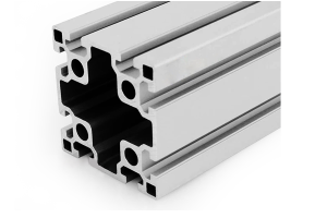 PG45 90×90 mm Eight Slot Heavy Aluminium Strut Profile for Heavy Machinery Frames
A 90 x 90 mm eight slot heavy PG45 aluminium strut profile with thicker…
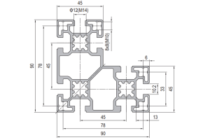 PG45 90×90 mm L-Shape Eight Slot Aluminium Strut Profile Corner Column for Frames
A 90 x 90 mm L-shaped eight slot PG45 aluminium strut profile with two…
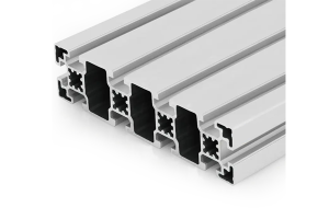 PG45 180 x 45 mm Ten Slot Aluminium Strut Profile Wide Gantry Beam
A 180 x 45 mm ten slot PG45 aluminium strut profile at about 6.20…
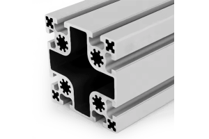 PG50 100×100 mm Eight Slot Aluminium Strut Profile for Heavy Machine Columns
A 100 x 100 mm eight slot PG50 aluminium strut profile with two slots…
 PG50 100×50 mm Six Slot Aluminium Strut Profile Rectangular Machine Beam
A 100 x 50 mm six slot PG50 aluminium strut profile with slots on…
