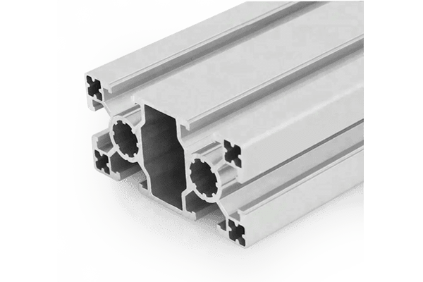
PG40 80×40 mm Six Slot Super Light Aluminium Strut Profile for Enclosures
An 80 x 40 mm six slot super light PG40 aluminium strut profile with reduced walls. For enclosure covers, exhibition frames and light guarding where weight matters more than tapped connections.
| Material | Aluminium |
|---|---|
| Alloy Grade | 6063-T5 |
| Temper | T5 |
| Section Size | 80 x 40 mm |
| Slot | 6 x 10.2 mm groove, 8 mm mouth, 40 mm pitch, outer pair 40 mm apart, M8 |
| Length | 6 m stock, cut to drawing to +/-0.5 mm |
| Tolerance | EN 755-9 / GB/T 6892, wall +/-0.15 mm |
| Surface | Mill finish / clear anodised / black anodised |
| MOQ | 300 |
| Lead Time | 18-28 days after deposit for mill finish |
| Loading Port | Shanghai / Ningbo |
| Supply Ability | 350 t per month |
| Payment Terms | T/T 30% deposit + 70% before shipment | L/C at sight |
| Trade Terms | FOB | CIF | EXW |
| Certifications | ISO 9001:2015 | EN 755-9 | RoHS | REACH |
Structural framing · PG40 super light beam
A PG40 80 x 40 mm six slot super light aluminium strut profile is a reduced-wall version of the standard 80 x 40 mm beam. The envelope, the slot layout, the 40 mm pitch, the 10.2 mm groove and the 8 mm mouth are all unchanged, so every standard 40 series bracket, nut, cap and cover still fits. It weighs about 2.1 kg/m against roughly 3.0 kg/m for a standard wall, and it is supplied in 6063-T5.
A super light section is a genuine engineering choice, not a cheap one, and it is worth knowing exactly what you are trading. Keeping the slot geometry identical means you keep the whole accessory system; thinning the walls means you lose two things that no bracket can restore — the ability to tap a thread, and the ability to clamp hard. Both of those follow directly from the wall thickness, and both have to be designed around rather than worked around.
What was kept and what was given up
The design of a super light section is deliberately conservative in one respect and aggressive in another. The external geometry is untouched, so the section is a drop-in replacement for the standard beam and no bracket has to be redesigned. The walls, however, are reduced, and that is where all the saving comes from.
| Standard 80 x 40 mm | Super light 80 x 40 mm | |
|---|---|---|
| Envelope | 80 x 40 mm | 80 x 40 mm |
| Slots | 6 x 10.2 mm on a 40 mm pitch | 6 x 10.2 mm on a 40 mm pitch |
| Slot mouth | 8 mm | 8 mm |
| Bracket compatibility | Standard 40 series | Standard 40 series |
| Weight | approx. 3.0 kg/m | approx. 2.1 kg/m |
| Bending stiffness | Reference | About 40 per cent of the reference |
| Tappable corner holes | Yes, with care | No |
| Slot torque ceiling | About 15 N m for M8 | About 8 to 10 N m for M8 |
The saving is in the wall, and so are the limits. A 30 per cent weight saving is worth having on a large cover or a long exhibition frame. It is not worth having if the design depends on a tapped connection or a heavily clamped joint, because neither can be recovered by using more hardware.
Limit one: you cannot tap it
A thread in aluminium needs about one diameter of engagement as an absolute minimum and one and a half diameters for full strength. An M8 thread therefore needs 8 to 12 mm of material. On a super light section the flange is well under half of that, so a tapped hole in the flange is not available at all — not marginal, but impossible.
The consequence is that every connection on a super light section has to go through a slot with a nut. That is a perfectly good method and it is how the whole system is designed to work, but it changes the design: you cannot bolt something to the end face of the beam, you cannot use an end face connector, and you cannot use a self-tapping screw connector. The connection vocabulary shrinks to brackets and slot nuts.
Limit two: the slot lip deforms
The slot mouth is an undercut — 8 mm wide against a 10.2 mm groove. The lip above that undercut is part of the flange, and on a super light section the flange is thin. When a nut is tightened, the load path goes from the nut, into the lip, and into the flange. If the lip deforms, the nut no longer sits square in the groove, the contact area drops, and the joint loosens under vibration.
In practice that means keeping the tightening torque down. A standard wall 40 series section will take about 15 N m on an M8 nut; on a super light section, stay around 8 to 10 N m. The rule that follows is worth writing into the assembly instructions: use more fixings rather than tighter ones.
| Fixing method | Available on a super light section? | What to do instead |
|---|---|---|
| Tapped hole in the flange | No, not enough wall | Use a slot nut in the groove |
| End face connector into the core bore | No, no thread available | Use a bracket, or choose a heavier section |
| Self-tapping screw connector | No, no thread can be formed | Use a bracket and slot nuts |
| M8 slot nut in the groove | Yes, the standard method | Torque to about 8 to 10 N m |
| Tapped hole in the 11 mm web | Marginal | Only where the web has the full wall thickness |
The load ceiling
With the section mounted the sensible way — the 80 mm dimension vertical, which gives about 43 cm4 — the deflection limits work out as follows for a simply supported beam at an L/500 limit.
| Span | Max distributed load at L/500 | Max central point load at L/500 | Verdict |
|---|---|---|---|
| 0.6 m | approx. 12.8 kN | approx. 8.0 kN | Fine for a frame rail |
| 0.8 m | approx. 7.2 kN | approx. 4.5 kN | Fine for a frame rail |
| 1.0 m | approx. 4.6 kN | approx. 2.9 kN | Fine for a cover or a guard |
| 1.2 m | approx. 3.2 kN | approx. 2.0 kN | Light loads only |
| 1.5 m | approx. 2.1 kN | approx. 1.3 kN | Add a mid support |
Those figures look generous until you put them next to the fixing limits. At a 1.2 m span the beam will carry 2 kN on paper, but the joints that hold it will have been torqued to 8 N m into a thin lip, and that is the real ceiling. On a super light frame the connections are almost always the limiting factor, not the section.
Building a super light frame
- Design every joint as a bracket and slot nut joint No end face connectors, no self-tapping connectors, no tapped holes. Decide this at the drawing stage, not on the bench.
- Keep the torque at 8 to 10 N m The slot lip is the limit. A torque wrench is worth having on a super light frame more than on a heavy one.
- Use more fixings, closer together A 40 mm pitch gives you plenty of positions. Six lightly loaded joints outperform two heavily loaded ones on a thin section.
- Mount the 80 mm dimension vertical It gives about four times the stiffness of the flat orientation. On a section this light the orientation is the difference between usable and unusable.
- Add a mid support rather than a heavier section if it sags On a cover or a guard a support is cheap; on a super light section it is usually the right answer anyway.
Frequently asked questions
Can I tap the end of a super light profile?
No. The flange is far too thin for an M8 thread, and even an M5 thread needs more material than is available. Every connection has to go through a slot with a nut.
What torque should I use?
About 8 to 10 N m for an M8 slot nut, against about 15 N m on a standard wall section. The limit is the deformation of the thin slot lip.
Is it strong enough for a machine guard?
For a guard panel frame, yes. A guard’s job is to retain a panel, and the panel carries the impact. For a guard that has to stop a projectile, size the frame on the impact load and expect to step up a wall thickness.
Will standard brackets fit?
Yes. The envelope and the slot geometry are identical to the standard 80 x 40 mm beam, so every 40 series bracket, nut, cap and cover fits unchanged.
How much lighter is it?
About 2.1 kg/m against roughly 3.0 kg/m, so about 30 per cent. On a large cover or a long exhibition frame that is a significant handling and freight saving.
Send the frame size and whether anything is tapped
Tell us the overall frame size, the load and whether any connection has to be tapped. We will confirm whether the super light wall works or whether you need the standard section.
Request a QuoteRelated Products
 PG45 90×90 mm Eight Slot Aluminium Strut Profile M10 Column Section
A 90 x 90 mm eight slot PG45 aluminium strut profile with 8 x…
 PG45 90×90 mm Eight Slot Heavy Aluminium Strut Profile for Heavy Machinery Frames
A 90 x 90 mm eight slot heavy PG45 aluminium strut profile with thicker…
 PG45 90×90 mm L-Shape Eight Slot Aluminium Strut Profile Corner Column for Frames
A 90 x 90 mm L-shaped eight slot PG45 aluminium strut profile with two…
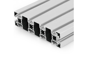 PG45 180 x 45 mm Ten Slot Aluminium Strut Profile Wide Gantry Beam
A 180 x 45 mm ten slot PG45 aluminium strut profile at about 6.20…
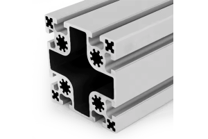 PG50 100×100 mm Eight Slot Aluminium Strut Profile for Heavy Machine Columns
A 100 x 100 mm eight slot PG50 aluminium strut profile with two slots…
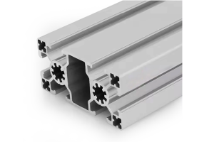 PG50 100×50 mm Six Slot Aluminium Strut Profile Rectangular Machine Beam
A 100 x 50 mm six slot PG50 aluminium strut profile with slots on…
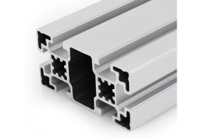 PG45 90×45 mm Six Slot Aluminium Strut Profile Rectangular Machine Beam
A 90 x 45 mm six slot PG45 aluminium strut profile for machine frames…
 PG45 90 x 45 mm Six Slot Aluminium Strut Profile Heavy Rectangular Beam
90 x 45 mm six-slot heavy aluminium strut profile with 10.2 mm grooves and…
