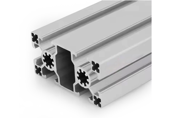
PG50 100×50 mm Six Slot Aluminium Strut Profile Rectangular Machine Beam
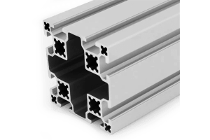
A 100 x 50 mm six slot PG50 aluminium strut profile with slots on all four faces, 6.8 x 6.8 mm M8 corner holes and a Ø12 mm M14 centre bore. A machine beam that carries a load and mounts the fittings.
| Material | Aluminium |
|---|---|
| Alloy Grade | 6063-T5 |
| Temper | T5 |
| Section Size | 100 x 50 mm |
| Slot | 6 x 10.2 mm groove, 8 mm mouth, 50 mm pitch on the 100 mm faces |
| Length | 6 m stock, cut to drawing to +/-0.5 mm |
| Tolerance | EN 755-9 / GB/T 6892, wall +/-0.15 mm |
| Surface | Mill finish / clear anodised / black anodised |
| MOQ | 150 |
| Lead Time | 22-32 days after deposit for mill finish |
| Loading Port | Shanghai / Ningbo |
| Supply Ability | 200 t per month |
| Payment Terms | T/T 30% deposit + 70% before shipment | L/C at sight |
| Trade Terms | FOB | CIF | EXW |
| Certifications | ISO 9001:2015 | EN 755-9 | RoHS | REACH |
Structural framing · PG50 machine beam
A PG50 100 x 50 mm six slot aluminium strut profile is a rectangular machine beam on a 50 mm slot pitch with a 10.2 mm groove and an 8 mm slot mouth. It carries two slots on each 100 mm face, 50 mm apart, one slot in the middle of each 50 mm face, 6.8 x 6.8 mm corner holes tapped M8 and a Ø12 mm centre bore tapped M14. The flange is 6 mm and the web 13 mm, and the section weighs about 5.4 kg/m. It is supplied in 6063-T5, cut and drilled to order.
The six slots are the point of the section. A machine beam is usually asked to do two jobs at once: carry a load along its length, and provide somewhere to fix the rail, the cable chain, the sensors and the guards. A two-slot beam can do the first job well and the second one badly, because everything has to land on the same two faces. Six slots on four faces let both jobs happen on the same member.
Where the six slots are
The count is not spread evenly, and the distribution is what makes the section useful. Both 100 mm faces get two slots on a 50 mm pitch. Each 50 mm face gets a single slot on its centreline. That is six in total, on four faces.
| Face | Slots | Spacing | Typical use |
|---|---|---|---|
| 100 mm face, top | Two | 50 mm apart | Linear rail, deck plate, mounting rail |
| 100 mm face, bottom | Two | 50 mm apart | Cross members, feet, brackets, guard fixings |
| 50 mm face, left | One | Centred | Cable chain, sensors, end stops, gussets |
| 50 mm face, right | One | Centred | Cable chain, sensors, end stops, gussets |
The narrow faces are the ones the two-slot beam does not have. A beam with slots only on its two wide faces forces every bracket, sensor and guard fixing onto the top or the bottom, where they compete with the rail and the cross members. The two side slots are what keeps those fixings out of the way.
Six slots against two
There is a two slot heavy version of this envelope in the range, and it is a good section — for a different job. The distinction is functional rather than structural: one is a load-bearing beam, the other is a machine beam.
| Two slot heavy 100 x 50 mm | Six slot 100 x 50 mm | |
|---|---|---|
| Slots | Two, one on each 100 mm face | Six, on all four faces |
| Faces with slots | Two | Four |
| Weight | approx. 6.20 kg/m | approx. 5.40 kg/m |
| Second moment, flat | approx. 50 cm4 | approx. 64 cm4 |
| Second moment, on edge | approx. 150 cm4 | approx. 201 cm4 |
| Designed for | Carrying a load along its length | Carrying a load and mounting several fittings |
| Weak point if misused | Nowhere to fix accessories | More slots means more edges to protect on anodised parts |
If the beam only has to carry something, the two slot heavy version is the honest answer and there is no reason to pay for four more slots. The moment the beam also has to mount a rail, a chain, two sensors and a guard, the six slot version stops being a convenience and starts being the cheaper option, because it removes brackets rather than adding them.
Which way round it goes
Like any flat rectangular section, this one has two very different second moments. Laid flat with the 100 mm face up it has about 64 cm4; stood on edge it has about 201 cm4.
That creates a choice about the rail. Flat, the beam is a convenient table surface but a soft one. On edge it is three times stiffer, and the rail then goes on the 50 mm face, which has only one slot and is the least useful mounting face. In practice most machine beams are used flat, because the stiffness is adequate for the span and the two wide faces are worth more than the stiffness.
Laying out a machine beam
- Put the rail on the top 100 mm face Two slots at 50 mm apart give the rail room and let it be adjusted along the beam without drilling.
- Put the cable chain on a 50 mm face The side slot is at mid height, which is where a chain or a drag anchor wants to run. It keeps the chain out of the rail’s working envelope.
- Put the sensors on the opposite 50 mm face Proximity switches and end stops on the far side stay clear of the chain and the operator.
- Keep the bottom face for structure Cross members, feet and gussets belong underneath. Leave the top face for the things that have to move.
- Bolt the ends through the M14 bore The end connection is the one that carries the beam’s load into the frame. Use the centre bore, not a slot.
- Plan the anodising Six slots means more edges. If the beam is anodised, say so at the ordering stage so the cut ends and any tapped holes are treated consistently.
Frequently asked questions
How is this different from the two slot heavy version?
Slot count and purpose. The two slot heavy version carries a load along its length; this one carries a load and also mounts a rail, a cable chain, sensors and guards on the same member.
Where are the six slots?
Two on each 100 mm face, 50 mm apart, and one in the middle of each 50 mm face.
Should I use it flat or on edge?
Flat for a machine table, where the two wide faces are worth more than the stiffness. On edge if it spans a long distance with a real load — about 201 cm4 against about 64 cm4.
Does it take 40 series slot nuts?
Yes. The groove is 10.2 mm and the mouth is 8 mm, the same as the 40 series, so standard M8 slot nuts fit.
What are the corner holes for?
They are 6.8 x 6.8 mm, tapped M8, and they take the end plates and the cross connections. The Ø12 mm centre bore is tapped M14 and takes the structural end bolt.
Can you drill the rail mounting holes?
Yes. Send DWG, DXF, STEP or PDF with the rail hole positions and the cut list, and we return the members cut, drilled and tapped to drawing.
Send the rail layout and the fittings list
Tell us what goes on the beam — rail, chain, sensors, guards — and where the load is. We will confirm the slot layout and the orientation, and quote cut lengths with the rail holes and the end connection machined to your drawing.
Request a QuoteRelated Products
 PG45 90×45 mm Six Slot Aluminium Strut Profile Rectangular Machine Beam
A 90 x 45 mm six slot PG45 aluminium strut profile for machine frames…
 PG45 90 x 45 mm Six Slot Aluminium Strut Profile Heavy Rectangular Beam
90 x 45 mm six-slot heavy aluminium strut profile with 10.2 mm grooves and…
 PG45 45 x 45 mm Two Slot Type B Aluminium Strut Profile Opposite Rail
45 x 45 mm two-slot Type B aluminium strut profile with slots on opposite…
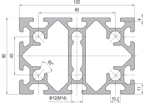 PG40 120 x 80 mm Ten Slot Aluminium Strut Profile Wide Heavy Beam
120 x 80 mm ten-slot aluminium strut profile with six slots on the two…
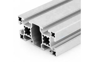 PG40 80×40 mm Six Slot Aluminium Strut Profile Standard Wall Beam
An 80 x 40 mm six slot standard wall PG40 aluminium strut profile. Two…
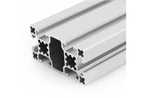 PG40 80×40 mm Six Slot Light Aluminium Strut Profile for Panel Frames
An 80 x 40 mm six slot light wall PG40 aluminium strut profile for…
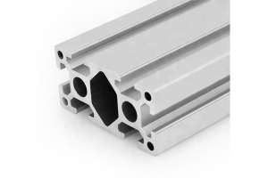 PG40 80 x 40 mm Six Slot Aluminium Strut Profile Heavy Rectangular Beam
80 x 40 mm heavy-wall six-slot aluminium strut profile with four slots on the…
 PG40 80×80 mm Eight Slot Aluminium Strut Profile Square Column
An 80 x 80 mm eight slot standard wall PG40 aluminium strut profile square…
