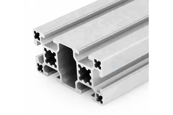
PG40 80×40 mm Six Slot Aluminium Strut Profile Standard Wall Beam
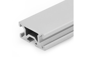
An 80 x 40 mm six slot standard wall PG40 aluminium strut profile. Two slots on each 80 mm face at the 40 mm pitch for joints that resist rotation, plus one slot on each 40 mm face for cross members.
| Material | Aluminium |
|---|---|
| Alloy Grade | 6063-T5 |
| Temper | T5 |
| Section Size | 80 x 40 mm |
| Slot | 6 x 10.2 mm groove, 8 mm mouth, 40 mm pitch, 2 slots per 80 mm face and 1 per 40 mm face, M8 |
| Length | 6 m stock, cut to drawing to +/-0.5 mm |
| Tolerance | EN 755-9 / GB/T 6892, wall +/-0.15 mm |
| Surface | Mill finish / clear anodised / black anodised |
| MOQ | 300 |
| Lead Time | 18-28 days after deposit for mill finish |
| Loading Port | Shanghai / Ningbo |
| Supply Ability | 400 t per month |
| Payment Terms | T/T 30% deposit + 70% before shipment | L/C at sight |
| Trade Terms | FOB | CIF | EXW |
| Certifications | ISO 9001:2015 | EN 755-9 | RoHS | REACH |
Structural framing · PG40 standard wall beam
A PG40 80 x 40 mm six slot aluminium strut profile is the standard wall beam of the 40 series range. Six 10.2 mm grooves with an 8 mm mouth are cut on a 40 mm pitch: two on each 80 mm face and one on each 40 mm face. The corners carry 5 x 5 mm bores and the web carries a 12 mm bore tapped M14 at the end. It weighs about 3.05 kg/m and is supplied in 6063-T5.
The 80 x 40 section is the workhorse of the range because it is the smallest beam that still puts two mounting positions on its working face. Those two slots are 40 mm apart, which is exactly one 40 series accessory pitch, so a bracket, a joining plate or a linear rail can be fixed in two places instead of one. That single detail is what makes the difference between a joint that holds and a joint that slowly rotates.
Two slots are not twice one slot
A single bolt in a single slot is a pivot. Whatever is bolted on can rotate about that bolt until something else stops it, and in a T-slot frame there is usually nothing else. The rotation is small at first, but it works the fixing loose, and a loose fixing in an aluminium groove deforms the slot lip.
Two bolts in two slots are a joint. The pair resists rotation directly, so the load path is a force and a moment rather than a force and a hope. On the 80 x 40 section the two slots on each 80 mm face are 40 mm apart, which is far enough apart for the couple to be effective even with modest bolt torque.
| Fixing arrangement | Resists rotation? | Load per bolt | Where it is acceptable |
|---|---|---|---|
| One bolt, one slot | No, it pivots | All of it | A purely locating pin, or a joint with a second positive stop |
| Two bolts, two slots on one face | Yes | Half each | The standard joint on this section |
| Two bolts, two faces | Yes, and resists twist about the beam | Half each | A bracket at a corner |
| Four bolts, two per face | Yes, strongly | A quarter each | A cantilever bracket or a rail end |
| One bolt plus a pin in a corner bore | Yes | Bolt carries shear, pin stops rotation | Where the groove is occupied |
A cantilever clamped in one slot will droop. Not because the section is weak, but because the joint rotates. On any bracket that sticks out more than about 150 mm, use two slots. It costs one extra bolt and it removes the whole failure mode.
Span against load
The figures below are for a simply supported beam at an L/500 deflection limit, which is the usual limit for a frame where alignment matters. On edge means the 80 mm dimension vertical, which is the way this section is almost always used.
| Span | On edge, distributed | On edge, central point | Flat, distributed | Flat, central point |
|---|---|---|---|---|
| 0.6 m | approx. 8.4 kN | approx. 5.2 kN | approx. 3.2 kN | approx. 2.0 kN |
| 0.8 m | approx. 4.7 kN | approx. 2.9 kN | approx. 1.8 kN | approx. 1.1 kN |
| 1.0 m | approx. 3.0 kN | approx. 1.9 kN | approx. 1.2 kN | approx. 0.72 kN |
| 1.2 m | approx. 2.1 kN | approx. 1.3 kN | approx. 0.81 kN | approx. 0.50 kN |
| 1.5 m | approx. 1.3 kN | approx. 0.83 kN | approx. 0.52 kN | approx. 0.32 kN |
| 2.0 m | approx. 0.75 kN | approx. 0.47 kN | approx. 0.29 kN | approx. 0.18 kN |
Note how quickly the flat figures fall away. Laid flat the section has about 24 cm4 against roughly 62 on edge, a factor of 2.6, so the same beam carries about a third of the load. A beam that is fine on edge at 1.5 m and gets installed flat will sag visibly.
Where the 40 mm face is used
The single slot on each 40 mm face is often treated as spare capacity, and on a simple frame it is. But it has three specific jobs that the 80 mm face cannot do.
The first is the perpendicular joint. When a 40 x 40 post meets the side of an 80 x 40 beam, the post’s end has to land on the 40 mm face, and a slot there gives the bracket somewhere to bolt. The second is a panel edge. A panel fixed to the 80 mm face would cover the two working slots; fixed to the 40 mm face it leaves them free. The third is a cross member coming in at right angles part way along the beam, which is a very common requirement in a machine guard.
Standard, light or heavy
The 80 x 40 section is made in three walls, and the choice between them is usually made on the wrong grounds. The table below sets out what actually changes.
| Super light | Light | Standard | Heavy | |
|---|---|---|---|---|
| Weight | approx. 2.10 kg/m | approx. 2.55 kg/m | approx. 3.05 kg/m | approx. 3.60 kg/m |
| Stiffness, on edge | approx. 43 cm4 | approx. 52 cm4 | approx. 62 cm4 | approx. 74 cm4 |
| Stiffness, flat | approx. 17 cm4 | approx. 20 cm4 | approx. 24 cm4 | approx. 29 cm4 |
| Tapped corner bores | No | Marginal | With care | Yes |
| Slot torque ceiling, M8 | 8-10 N m | 10-12 N m | About 15 N m | About 18 N m |
| Best for | Covers, display frames | Panels, light guards | General machine framing | Concentrated loads, tapping |
The stiffness range across the four walls is only 1.7 to 1. The weight range is the same 1.7 to 1. So on this section, choosing a heavier wall buys stiffness and weight in the same proportion — it does not make the section more efficient. What the heavy wall does buy that the others cannot is the ability to tap a thread and to clamp a nut hard without deforming the slot lip.
Frequently asked questions
Why does the 80 mm face have two slots?
Because two slots 40 mm apart let a bracket or a rail be fixed at two points, which is what stops the fitting rotating. One slot is a pivot; two slots are a joint. The 40 mm spacing is one 40 series accessory pitch, so standard parts line up with both.
What is the single slot on the 40 mm face for?
Perpendicular joints, panel edges and cross members. When a post or a cross member comes in at right angles to the beam, it lands on the 40 mm face, and the slot there is what the bracket bolts into.
Which wall thickness should I choose?
Standard for general machine framing. Light where the beam is carrying panels or light guards rather than a machine. Heavy only where the load is concentrated or the design needs a tapped thread. On this section the walls differ by only 1.7 to 1 in stiffness, so the wall is not the lever that fixes a deflection problem.
How far can it span?
On edge at an L/500 limit, about 1.5 m for a 1.3 kN distributed load or about 0.83 kN central. Beyond 1.5 m the section starts to want a mid support rather than a heavier wall.
Can I tap the corner bores?
On the standard wall, with care — the 5 x 5 mm corner bores are primarily clearance holes. If the design depends on a tapped connection, the heavy wall is the version that supports it properly.
Send the span, the load and the orientation
Tell us the span, the load and whether the beam runs on edge or flat. We will confirm the section and, if it is marginal, say whether a mid support or a deeper section is the better answer.
Request a QuoteRelated Products
 PG40 80×40 mm Six Slot Light Aluminium Strut Profile for Panel Frames
An 80 x 40 mm six slot light wall PG40 aluminium strut profile for…
 PG40 80 x 40 mm Six Slot Aluminium Strut Profile Heavy Rectangular Beam
80 x 40 mm heavy-wall six-slot aluminium strut profile with four slots on the…
 PG40 80×80 mm Eight Slot Aluminium Strut Profile Square Column
An 80 x 80 mm eight slot standard wall PG40 aluminium strut profile square…
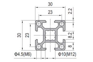 PG30 30×30 mm Four Slot Aluminium Strut Profile Standard Wall Column
A 30 x 30 mm four slot standard wall PG30 aluminium strut profile square…
 PG20 20 x 20 mm Four Slot Aluminium Strut Profile Miniature Frame
20 x 20 mm four-slot aluminium strut profile with 6.2 mm grooves and 6…
 PG20 20 x 20 mm R90 Two Slot Aluminium Strut Profile Rounded Corner
20 x 20 mm quarter-round aluminium strut profile with a swept R90 outer corner…
 PG20 40 x 20 mm Six Slot Aluminium Strut Profile Rectangular Flat Beam
40 x 20 mm six-slot aluminium strut profile with 6.2 mm grooves on a…
 PG15 30 x 15 mm Three Slot Aluminium Strut Profile Light Panel Frame
30 x 15 mm three-slot aluminium strut profile with 6 mm grooves on a…
