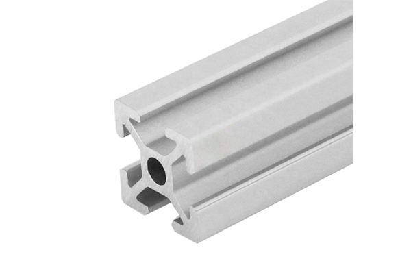
PG20 20 x 20 mm Four Slot Aluminium Strut Profile Miniature Frame
20 x 20 mm four-slot aluminium strut profile with 6.2 mm grooves and 6 mm mouths. The smallest standard four-slot section for miniature frames using M5 and M6 fasteners.
| Material | Aluminium |
|---|---|
| Alloy Grade | 6063-T5 |
| Temper | T5 |
| Section Size | 20 x 20 mm |
| Slot | 4 x 6.2 mm groove, 6 mm mouth, 20 mm pitch, 1 slot per face, M5 and M6 |
| Length | 6 m stock, cut to drawing to +/-0.5 mm |
| Tolerance | EN 755-9 / GB/T 6892, wall +/-0.15 mm |
| Surface | Mill finish / clear anodised / black anodised |
| MOQ | Made to order; small trial lengths available from stock offcuts |
| Lead Time | Typically 2 to 3 weeks for mill finish, about a week longer for anodising |
| Loading Port | Shanghai, Ningbo, Qingdao |
| Supply Ability | Extrusion capacity for standard and custom dies, with in-house cutting, machining and anodising |
| Payment Terms | T/T 30 per cent deposit, balance against copy of bill of lading; L/C at sight for larger orders |
| Trade Terms | FOB, CIF, CFR, EXW |
| Certifications | Mill certificate to EN 10204 3.1 on request, RoHS and REACH declarations |
01What is the 20 x 20 mm four slot profile?
What makes the 20 series the entry-level T-slot profile?
It is the smallest standard section that still gives you four T-slots, one on each face. The 6.2 mm groove and 6 mm mouth accept M5 and M6 slot nuts, which are the smallest practical sizes for aluminium frame assembly. Below this, you are in the 15 series with M4 fasteners, which is really only for display cases and very light panels.
How much load can a 20 x 20 frame carry?
Not much. The section weighs 0.62 kg/m, and the effective wall at the slot lip is about 1.5 mm. An M6 slot nut in a 6.2 mm groove has a rated pull-out of about 0.5 kN, roughly a third of what the same nut achieves in a 40 series groove. A 1 m simply supported beam deflects about 0.8 mm under a 50 N centre load. The 20 series is for instrument housings, cable trays and small guard panels, not for structural frames.
Can I upgrade from 20 series to 30 series later?
No, not without redesigning every joint. The 30 series has an 8.2 mm groove and 8 mm mouth, so 20 series nuts and bolts do not fit. The decision between 20 and 30 series has to be made at the design stage, based on the load and the fastener size the frame needs.
02Section data
| Item | Value | Note |
|---|---|---|
| Envelope | 20 x 20 mm square | smallest four-slot standard section |
| Slots | 4 | 6.2 mm groove, 6 mm mouth, one per face |
| Slot pitch | 20 mm between centres | across the diagonal |
| Central bore | approx. Phi4 mm | for through-bolts or location |
| Wall | approx. 1.5 mm at slot lip | thinnest point of the section |
| Weight | approx. 0.62 kg/m | from published specification |
| Alloy | 6063-T5 | EN AW-6063 |
| Standard | EN 755-9 / GB/T 6892 | wall tolerance +/-0.15 mm |
| Length | 6 m stock | cut to drawing to +/-0.5 mm |
The weight and wall figures are from the published product specification. The 1.5 mm wall at the slot lip is the thinnest point and drives the pull-out force rating. If a joint needs more tension, use the central bore with a through-bolt instead of the slots.
03Where the 20 series fits in the range
The 20 series is the bottom of the T-slot range. Below it is the 15 series (M4 fasteners, display only), and above it is the 30 series (M6/M8, light structural). The 20 series fills the gap where the frame is too small for 30 series but too functional for 15 series.
- Instrument housings and sensor enclosures: the 20 x 20 is small enough to sit behind a panel, and the four slots give mounting on all sides.
- Cable trays and wire routing frames: the 6.2 mm groove holds cable clips and cover strips, and the 0.62 kg/m weight keeps the frame negligible.
- Small guard panels and access doors: where the guard is a barrier, not a load-bearing structure, and M5 fasteners are sufficient.
- Prototype and jig frames: the 20 series is cheap enough to use for temporary fixtures and test rigs that will be dismantled.
In all these, the 20 series is chosen because the load is light and the space is tight. If either of those changes, the 30 series is the next step up.
04Fastener compatibility and slot pull-out
The 6.2 mm groove and 6 mm mouth accept the full 20 series accessory range: M5 and M6 slot nuts, hammer head T-bolts, cover strips, hinges and end caps. The slot nut grips the groove lips from behind, and the effective engagement length is the wall thickness at the lip, about 1.5 mm.
| Fastener | Groove fit | Pull-out force | Typical torque |
|---|---|---|---|
| M5 slot nut | 6.2 mm groove, snug | approx. 0.4 kN | 2 to 3 Nm |
| M6 slot nut | 6.2 mm groove, snug | approx. 0.5 kN | 3 to 4 Nm |
| M5 T-bolt | 6.2 mm groove, hammer head | approx. 0.4 kN | 2 to 3 Nm |
| M6 T-bolt | 6.2 mm groove, hammer head | approx. 0.5 kN | 3 to 4 Nm |
| Through-bolt (central bore) | Phi4 mm bore | full bolt rating | as bolt spec |
The pull-out figures are estimates based on the 1.5 mm wall at the slot lip. They are lower than the 30 and 40 series because the wall is thinner. For structural tension, use the central bore with a through-bolt.
05Bending performance and span limits
The 20 x 20 section has a second moment of area of about 0.2 cm4 about each principal axis. That is small, and it limits the span to short distances before deflection becomes unacceptable.
| Span (mm) | Self-weight deflection | Deflection at 50 N centre load |
|---|---|---|
| 300 | negligible | 0.07 mm |
| 500 | 0.03 mm | 0.20 mm |
| 750 | 0.10 mm | 0.45 mm |
| 1000 | 0.24 mm | 0.80 mm |
| 1500 | 1.2 mm | 2.7 mm |
As a rule of thumb, a 20 x 20 member used as a beam should not span more than 500 mm without an intermediate support. For longer spans, step up to the 30 series or use a truss arrangement.
06Choosing between the 20 series and the 30 series
Choose the 20 series
- The frame carries light loads: instruments, cables, small panels
- Space is tight and the 20 mm envelope is the maximum
- Weight matters: the 0.62 kg/m is lighter than the 30 series 0.7 kg/m
- M5 fasteners are sufficient for the joint loads
- The frame is temporary or prototype and cost is the driver
Choose the 30 series
- The frame carries bending load or spans more than 500 mm
- You need M6 or M8 fasteners for higher joint tension
- Vibration resistance matters: the 30 series wall is thicker
- The frame is permanent and needs more stiffness
- You want the wider accessory range of the 30 series
07Failure modes to design out
| What goes wrong | Why it happens | Design it out by |
|---|---|---|
| Slot nut pulls out under load | the 1.5 mm wall gives low engagement | use the central bore with a through-bolt for structural tension |
| Beam deflects too much | the second moment of area is only 0.2 cm4 | keep spans under 500 mm or add an intermediate support |
| Frame racks under lateral load | the corner joints are weak with M5 fasteners | use corner brackets or gusset plates at every joint |
| Slot nut deforms the groove lip | overtightening an M6 nut in a 1.5 mm wall groove | keep torque under 4 Nm; use the through-bolt for higher clamping |
| Cover strip pops out | the 6 mm mouth is narrow and the strip clip is light | specify a friction-fit strip, not a snap-in strip, for the 20 series |
08What to check before you order
Procurement checklist for the 20 x 20 four-slot
- Confirm the fastener size: M5 or M6. If you need M8, step up to 30 or 40 series.
- Confirm the span: any member over 500 mm needs an intermediate support or a bigger section.
- Confirm the finish: mill for hidden frames, anodised for exposed service.
- Confirm the quantity in metres. A 6 m bar yields twelve 480 mm members.
- Confirm whether the central bore is needed. Not all 20 series dies have one.
- If the frame carries lateral load, add corner brackets at every joint. M5 slot nuts alone will not prevent racking.
09Terms used on this page
- Slot lip
- The edge of the groove mouth that the slot nut grips from behind. Its thickness determines the pull-out force.
- Pull-out force
- The force required to pull a slot nut out of the groove. It is proportional to the wall thickness at the lip.
- Second moment of area
- A geometric property of the section, in cm4, that determines bending stiffness. The 20 x 20 has about 0.2 cm4.
- Through-bolt
- A bolt that passes through the central bore, tying two members together in tension. Independent of the slots.
- Racking
- The lateral deflection of a frame when a force is applied to one corner. Corner brackets resist racking.
10Questions buyers ask
Can I use M8 fasteners in the 20 series?
No. The 6.2 mm groove and 6 mm mouth are designed for M5 and M6 slot nuts. M8 nuts require the 8.2 mm groove of the 30 series or the 10.2 mm groove of the 40 series.
What is the maximum span for a 20 x 20 beam?
About 500 mm without an intermediate support. Beyond that, deflection under even modest load becomes noticeable. For longer spans, use the 30 series or add a support.
What is the difference between the 20 series and the 15 series?
The 15 series has a 6 mm groove and accepts M4 fasteners. It is for display cases and very light panels. The 20 series has a 6.2 mm groove, M5 and M6 fasteners, and four slots, making it the smallest practical section for functional frames.
What is the weight per metre?
Approximately 0.62 kg/m, from the published product specification.
Can it be supplied anodised?
Yes. Clear, black, champagne and bronze are standard anodised colours at 10 to 15 micron. Mill finish is available for hidden frames.
What is the lead time?
Typically two to three weeks for mill finish, with anodising adding about a week.
What we need to quote this section
- The section drawing or the profile reference GP-SP-2020-4S.
- The cut length for each member and the number of members.
- The end preparation: square cut, mitre, or pre-drilled.
- The finish: mill, clear anodised, or a specified colour.
- The annual or per-order quantity, in metres or pieces.
- Any certification requirement: mill certificate to EN 10204 3.1.
Send those six items and the quotation comes back with the extrusion price, the cutting charge, the finish surcharge and the lead time broken out separately. Browse the full aluminium profile catalogue and the 20 series aluminium profiles range for related sections.
Need this section quoted for your miniature frame?
Send the section, the cut list and the finish. We quote extrusion, cutting and anodising as separate lines so the cost of each step is visible.
Request a quotationRelated Products
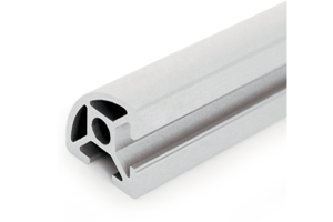 PG20 20 x 20 mm R90 Two Slot Aluminium Strut Profile Rounded Corner
20 x 20 mm quarter-round aluminium strut profile with a swept R90 outer corner…
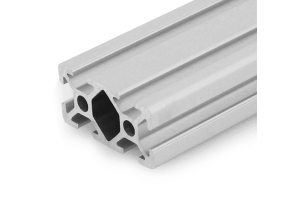 PG20 40 x 20 mm Six Slot Aluminium Strut Profile Rectangular Flat Beam
40 x 20 mm six-slot aluminium strut profile with 6.2 mm grooves on a…
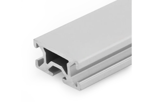 PG15 30 x 15 mm Three Slot Aluminium Strut Profile Light Panel Frame
30 x 15 mm three-slot aluminium strut profile with 6 mm grooves on a…
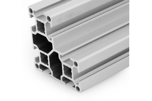 PG30 60×60 mm L-Shape Eight Slot Aluminium Strut Profile Corner Column
A 60 x 60 mm L-shape eight slot PG30 aluminium strut profile corner column…
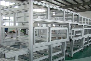 Aluminium Profile Shelf System 40×40 mm T-Slot Uprights for Workshop Racking
A bolted aluminium profile shelf system in 40 x 40 mm T-slot uprights and…
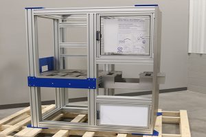 Aluminium Extrusion Table Frame 20×20 40 mm Workbench Base
20 series aluminium extrusion table frame with 40x40 mm four-slot legs and 40x80 mm…
Aluminium Framing Extrusion Kit 40×40 mm 40 Series Cut List for Machine Frames
A cut-to-length aluminium framing extrusion kit in the 40 series: profile cut to a…
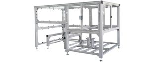 Aluminium Profile Machine Guard Frame 40 x 40 mm Safety Enclosure
40 x 40 mm T-slot aluminium machine guard frame for safety fences and enclosures,…
