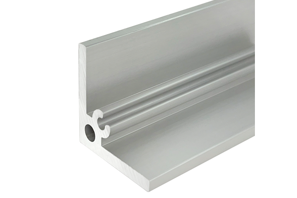
Aluminium Angle Extrusion 40x40x5 mm for Frame Assembly and Bracing
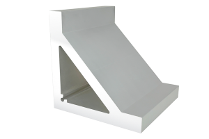
40 x 40 x 5 mm aluminium angle extrusion in 6061-T6 for frame assembly and bracing. Solid section, drilled and tapped to drawing, with M6 and M8 threads in the 5 mm wall.
| Material | Aluminium |
|---|---|
| Alloy Grade | 6061-T6 |
| Temper | T6 |
| Section Size | 40 x 40 x 5 mm equal leg angle |
| Slot | Solid angle, no slot; assembles with 40 series 8.2 mm slot T-nuts |
| Length | Saw cut to length, ends square or 45 degree mitre, +/-0.5 mm |
| Tolerance | EN 755-9, wall +/-0.15 mm; hole position +/-0.2 mm |
| Surface | Mill finish / clear anodised / black anodised |
| MOQ | Made to order; small quantities from stock |
| Lead Time | Typically 1 to 2 weeks for cutting and drilling, plus a week for anodising |
| Loading Port | Shanghai, Ningbo, Qingdao, Shenzhen |
| Supply Ability | In-house saw cutting, drilling, tapping and CNC machining |
| Payment Terms | T/T 30 per cent deposit, balance against copy of bill of lading |
| Trade Terms | FOB, CIF, CFR, EXW |
| Certifications | Mill certificate to EN 10204 3.1 on request, RoHS and REACH declarations |
01What is this angle used for?
This is the 40 x 40 x 5 mm aluminium angle extrusion, and it answers a specific job: taking a T-slot frame from a loose set of profiles and making it a rigid shape. The angle bolts across a corner, ties a panel to a frame, or braces a bay against racking. It is a solid 6061-T6 section with a 5 mm wall, so it takes M6 and M8 threads properly, unlike the thin bent angle that strips out after two rebuilds.
The page below is not about the section, it is about working the section: where to put the holes, how far the hole has to sit from the edge, how much thread a 5 mm wall actually gives you, and how the cut tolerances stack up across a frame.
Can I tap M8 into a 5 mm wall?
Yes, but the thread engagement is short. A 5 mm wall gives 7 full threads on an M8 (1.25 mm pitch) and 8 threads on an M6 (1.0 mm pitch). That is enough for a static joint in 6061-T6 but not enough for a joint that is opened and closed repeatedly. Add a T-nut or a nut on the back face for anything that gets rebuilt.
How far must a hole sit from the edge?
At least 2x the hole diameter, and on 6061-T6 I prefer 2.5x. An M8 hole should be at least 16 mm from the edge and preferably 20 mm. Closer than that and the bolt will tear out the edge under load, no matter how strong the alloy is.
02Machining the angle: cut, drill, tap, deburr
The angle arrives as a stock length. Four operations turn it into a part, and each one has a tolerance that feeds the frame’s final accuracy.
| Operation | Tool | Held to | Feeds the frame as |
|---|---|---|---|
| Cut to length | CNC saw, carbide blade | +/-0.5 mm | frame diagonal grows 0.7 mm |
| Mitre cut | CNC saw, 45 degree | +/-0.5 degrees | corner gap up to 0.3 mm |
| Drill | CNC or radial drill, HSS or carbide | +/-0.2 mm position | bolt pulls the joint to position |
| Tap | machine tap, M6 or M8 | 6H class | thread engagement on the wall |
| Deburr | hand or vibratory | no burr over 0.1 mm | parts seat flat |
The two cuts matter most. A frame is a closed loop of members, so the length errors add up around the loop and then have to go somewhere: they close up as an out-of-square frame or as a bow in one member. Holding the cut to ±0.5 mm keeps the accumulated error under a millimetre on a normal four-sided frame.
The deburr is not cosmetic. A 0.2 mm burr on the end face stops the angle seating flat against the member it is bolted to, and the joint then flexes. Specify a deburred face, and specify the face that becomes the datum.
03Mixing a solid angle with a T-slot profile
The common assembly in this catalogue is a solid angle bolted to a T-slot profile. The T-slot side has a slot with a known width, and the bolt has to match it. The table below maps our slot series to the bolts and T-nuts that fit.
| Slot series | Slot width | Fits bolts | T-nut to use | Typical angle |
|---|---|---|---|---|
| 20 series | 6.2 mm | M5, M6 | 20 series T-nut | 20 x 20 x 3 mm |
| 30 series | 8.2 mm | M6, M8 | 30 series T-nut | 30 x 30 x 4 mm |
| 40 series | 8.2 mm | M6, M8 | 40 series T-nut | 35 x 35 x 4 mm |
| 45 series | 10.2 mm | M8, M10 | 45 series T-nut | 40 x 40 x 5 mm |
| 50 series and up | 10.2 mm | M8, M10, M12 | heavy series T-nut | 50 x 50 x 9 mm |
The sequence matters. Drop the T-nut into the slot first, slide it to the hole position, then bring the angle up and start the bolt by hand before you torque it. If you torque a bolt into a T-nut that is not seated, the nut rotates 90 degrees in the slot and locks; the only way out is to cut the bolt.
Hole pattern for the common joint
- Corner joint, 40 series: two M8 holes 20 mm apart on the 40 mm leg, both 20 mm from the inside corner.
- Panel to frame: M6 holes at 150 to 200 mm pitch, 15 mm from the edge.
- Diagonal brace: M8 at each end, hole centre at half the leg length so the bolt sits on the neutral axis.
- Base to floor: M10 or M12 through the angle and into an anchor, hole at least 20 mm from the edge.
04How the tolerance chain accumulates in a frame
A frame of four angle-braced members is a closed loop of tolerances. Each contribution is small; the loop sum is what you see as an out-of-square frame.
| Contribution | Per joint | In a 4-corner frame | Effect |
|---|---|---|---|
| Cut length error | +/-0.5 mm | +/-1.0 mm on a side | frame width varies |
| Mitre squareness | +/-0.5 deg | +/-1.0 deg | corner gap or step |
| Hole position error | +/-0.2 mm | +/-0.4 mm | bolt pulls the joint to position |
| Hole clearance M8 normal | +0.2 to +0.5 mm | absorbs the above | small, forgiving |
| Bolt hole in slotted form | up to +2 mm | absorbs a lot | adjustable, less rigid |
The practical conclusion: cut length and mitre squareness dominate. Hole position errors are absorbed by the bolt clearance. Buyers who are chasing a square frame should spend their tolerance budget on the saw, not on the drill.
05Choosing the section for the joint
Choose the solid angle
- The corner takes a real moment from a panel or a load
- You need threads you can tighten without a T-nut
- The joint is bolted to a flat face, not into a slot
- You want a visible finished corner with no slot is visible
- The assembly gets rebuilt and needs to survive it
Choose a T-slot profile gusset
- The joint is inside a slot, with no flat face to land on
- You need the joint to be adjustable after assembly
- The frame is taken apart often, so T-nuts are wanted
- You want a flush corner with no external angle
- The frame is all in one profile family and the buyer wants one bill of materials
06Failure modes on an assembled corner
| What goes wrong | Why it happens | Design it out by |
|---|---|---|
| Thread strips in the 5 mm wall | M8 in a 5 mm wall is only 7 threads, re-torqued too often | use M6, or add a T-nut or a back-face nut |
| Bolt tears out the edge | hole under 2x the diameter from the edge | keep M8 at least 16 mm, ideally 20 mm, from the edge |
| Corner rocks under load | the angle is bolted to a T-slot face that is not flat | seat the angle on the profile face, not on the slot lip |
| Frame will not go square | cumulative cut and mitre error in a closed loop | hold the cut to +/-0.5 mm and the mitre to +/-0.5 degrees |
| Anodised angle will not earth | the anodised film is an insulator | mask a bonding pad or grind a patch back to bare metal |
| Joint loosens in service | vibration on a static joint | use a serrated washer or a thread-locking compound |
07What to check before you order a drilled angle
Procurement checklist for a drilled and tapped angle
- Confirm the section: for example 40 x 40 x 5 mm.
- Confirm the alloy and temper: 6061-T6 is standard.
- Send the hole pattern as a drawing, with edge distances.
- Confirm the thread: M6 or M8, and whether a T-nut is used.
- Confirm the end cut: square or 45 degree mitre.
- Confirm the deburr requirement and the datum face.
- Confirm the finish, and mask the bonding point if earthing matters.
- Confirm the quantity and the packing.
08Questions buyers ask
Can you drill and tap the angle to my drawing?
Yes. Send the drawing with hole positions, thread sizes and edge distances, and we drill and tap to ±0.2 mm hole position.
How much thread does a 5 mm wall give?
Seven threads on an M8 and eight on an M6. That is fine for a static joint, but add a T-nut or a back-face nut for a joint that is taken apart often.
What bolt fits the 40 series slot?
The 40 series slot is 8.2 mm wide and takes M6 and M8 with a 40 series T-nut.
How square will the finished frame be?
With a ±0.5 mm cut and a ±0.5 degree mitre, a four-sided frame stays within about 1 mm on the diagonal.
Can the angle be anodised after drilling?
Yes. The anodising covers the cut and drilled faces; if the joint has to earth, mask a bonding point first.
What is the lead time?
One to two weeks for cutting, drilling and tapping, plus a week if anodising.
What we need to quote a drilled angle
- The section and wall: for example 40 x 40 x 5 mm.
- The alloy and temper.
- The hole pattern drawing, with edge distances and thread sizes.
- The end cut: square or mitre, and the angle.
- The finish, and any bonding point to mask.
- The quantity in pieces or metres.
Send those six items and the quotation comes back with the cutting, drilling, tapping and finish broken out separately. Browse the connecting elements range and the 40 series strut profiles that this angle is usually assembled with.
Have a frame assembly that needs a drilled angle?
Send the hole pattern and the member list. We quote the angle, the cutting, the drilling and the finish as separate lines.
Request a quotationRelated Products
 Custom Aluminium Extrusion Profile 20 to 100 mm, 6063-T5
Aluminium extrusion profiles supplied to Canada in 6063-T5 and 6061-T6, mill or anodised, with…
 Aluminium Extrusion for Sale 20 to 100 mm Stock Lengths Cut to Size 6063 T5
Aluminium extrusion for sale in three routes: stock lengths, cut to size or a…
 Aluminium Extruders 600 to 4000 Ton Press Capacity 40 to 160 mm Profile
Aluminium extrusion capacity across 600 to 4000 tonne presses, covering profiles up to about…
 Aluminium Extrusion Manufacturing Factory: 20 to 100 mm Profiles
Aluminium extrusion profiles for Gujarat, India, in 6063-T5 and 6061-T6, with anodising film selected…
 Aluminium Extrusion Manufacturers: 30 to 60 Series, 8 mm Slot
Aluminium extrusion profiles for Delhi NCR, India, in 6063-T5. Strut sections from 30 to…
 Aluminium Extrusion Profile Supply: 15 to 45 Series Kits, 8 mm Slot
Aluminium extrusion profile supply for Ahmedabad in 6063-T5: electrical cabinet frames with a designed…
 Aluminium Extrusion Profiles 20 to 45 Series for OEM, up to 100 mm
Aluminium extrusion profiles for Tamil Nadu in 6063-T5, with full batch traceability from heat…
 Aluminium Extrusion Manufacturer: 45 to 120 mm, 6063-T5
Aluminium extrusion for Chennai in 6063-T5, section supply with port logistics support through Chennai…
