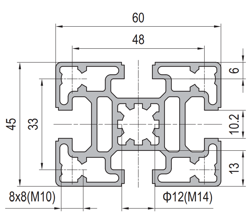
45 x 60 mm Aluminium Profile for Textile Machine Frames
45 x 60 mm four-slot aluminium extrusion in 6063-T5 for loom, winder and conveyor frames. 2.8 kg/m with 10.2 mm slots, or 3.3 kg/m with 8 mm slots, supplied cut and drilled to the frame drawing.
| Material | Aluminium |
|---|---|
| Alloy Grade | 6063-T5 |
| Temper | T5 |
| Section Size | 45 x 60 mm, four slots |
| Slot | 4 x 10.2 mm groove, 10 mm mouth, M8; or 8 mm groove with M10 slot nuts on a 33 mm pitch |
| Length | 6 m stock; cut to frame list to +/-0.5 mm |
| Tolerance | EN 755-9, wall +/-0.15 mm; straightness 1.5 mm per metre; twist 2 degrees |
| Surface | Mill finish, or anodised AA15 to EN ISO 7599; clear or black |
| MOQ | 150 m |
| Lead Time | 20 to 28 days after deposit for mill finish, about one week longer for anodising |
| Loading Port | Shanghai / Ningbo |
| Supply Ability | 600 t per month extrusion with in-house anodising |
| Payment Terms | T/T 30% deposit + 70% before shipment | L/C at sight |
| Trade Terms | FOB | CIF | EXW |
| Certifications | Mill certificate per heat, coating thickness report per lot, RoHS and REACH declarations |
01What excitation does a loom frame actually see?
Three sources, and they sit in different frequency bands. The first is the main shaft: a loom running at 600 picks per minute gives a 10 Hz fundamental. The second is the harmonic series above it, at 20, 30 and 40 Hz, which is where most of the energy above the fundamental actually lives. The third is the beat-up and the weft insertion, which are impacts rather than sinusoids and therefore put broadband energy into the frame, including at frequencies well above the running speed.
For a winder or a package conveyor the picture is simpler: one dominant frequency from the drive, plus a once-per-revolution component from any imbalance in the spindle or the package. Both are usually below 30 Hz.
| Machine | Running speed | Dominant excitation | Where the frame hurts |
|---|---|---|---|
| Loom, 600 picks per minute | 10 Hz fundamental | 10, 20, 30, 40 Hz harmonics plus beat-up impacts | Any frame mode between 25 and 45 Hz |
| Loom, 800 picks per minute | 13.3 Hz fundamental | 13.3 to 53 Hz harmonics | Any frame mode between 35 and 55 Hz |
| Winder | Drive dependent, usually 15 to 25 Hz | Drive frequency plus once per revolution | Frame modes within 20 percent of the drive |
| Package conveyor | 5 to 15 Hz | Chain or belt frequency | Frame modes near the chain frequency |
The useful rule is not “make the frame stiff”. It is “keep the first frame mode away from the harmonic band”. A frame at 34 Hz on a 600 rpm loom is 13 percent from the 30 Hz harmonic, which is inside the range where a small change in preload or belt tension moves the mode onto the excitation.
02How do you estimate the natural frequency of a 45 x 60 span?
For a uniform beam with distributed mass and simple supports, the first bending mode is:
f1 = (pi / 2) x sqrt( EI / (m x L^4) )
where E is 69,000 N/mm2 for 6063-T5, I is the second moment of area about the bending axis in mm4, m is mass per unit length in kg/m, and L is the span in metres. The same number can be reached from the mid-span stiffness k = 48EI/L3 and the modal mass, which is 0.49 of the total mass for a simply supported beam; the two routes agree, and checking both is a good way to catch an arithmetic slip.
| Span | 45 x 60 at 2.8 kg/m | 45 x 60 at 3.3 kg/m | 45 x 90 at 4.10 kg/m |
|---|---|---|---|
| 1.2 m | 76 Hz | 80 Hz | 100 Hz |
| 1.5 m | 49 Hz | 51 Hz | 64 Hz |
| 1.8 m | 34 Hz | 36 Hz | 44 Hz |
| 2.1 m | 25 Hz | 26 Hz | 33 Hz |
| 2.4 m | 19 Hz | 20 Hz | 25 Hz |
These are calculated, not measured: I is estimated at 20 cm4 for the 2.8 kg/m section, 26 cm4 for the 3.3 kg/m section and 68 cm4 for 45 x 90, all on a 2.5 mm nominal wall with the slot openings deducted approximately. Treat them as a screening tool. A frame with bolted joints will measure lower than this, because the joints are not rigid.
03Why does dynamic stiffness matter more than static stiffness?
Static stiffness tells you how far the frame moves under a steady load. Dynamic stiffness tells you how it responds to a load that changes direction ten times a second, and the two are related through damping and mass, not through the section alone. A frame can pass a deflection check at 1.8 m and still vibrate visibly, because the deflection check uses a load the frame never actually sees.
The transmissibility curve is the practical version of this. Below about 0.7 times the natural frequency the frame follows the machine almost rigidly. Between 0.7 and 1.4 times it amplifies. Above about 1.4 times it starts to isolate. That is why the target is either well below or well above the excitation, never in between, and why adding mass to a frame that is already resonant makes it worse rather than better.
Static view
- Deflection under a rated load, checked against L/360
- Says nothing about frequency
- Easy to pass with a heavier section
- Explains why a frame that passes still shakes
Dynamic view
- First mode frequency against the excitation band
- Joint stiffness enters directly, often halving the calculated value
- A heavier section lowers the frequency if I grows slower than mass
- Explains why the same frame behaves differently on two machines
04Where does micro-sliding destroy the joint?
At the faying surface inside the connection. An M10 bolt at 30 Nm develops roughly 17 to 20 kN of preload. With a friction coefficient of about 0.15 between two anodised aluminium faces, the slip resistance per interface is around 2.5 to 3 kN. Under a static load that is a large margin; under a reversing load it is a fatigue question, not a strength question.
The failure mode is fretting. Small relative movement, on the order of a few micrometres per cycle, breaks the anodic film, exposes bare aluminium, and generates oxide debris that is harder than the parent metal. The debris accumulates in the joint, the preload drops as the joint beds in, and the movement grows. The frame does not break; it loosens, and then it rattles at a frequency that has nothing to do with the machine’s running speed.
- Use a hardened washer under the head and under the nut; without one, the aluminium yields locally and the preload is lost in the first week.
- Re-torque after the first 100 hours, then at the first service interval. Bedding in accounts for most of the preload loss.
- Keep the joint dry and free of release agents. A lubricated joint has a lower friction coefficient and therefore lower slip resistance, which is the opposite of what people expect.
- Prefer a connector that engages both slot flanges over a single central bolt; the load path is shorter and the faying area larger.
05Should you isolate the foot or stiffen the frame?
Isolate the foot when the frame is already stiff enough and the problem is transmission into the floor or into a neighbouring machine. Stiffen the frame when the problem is relative movement inside the frame itself, which is what shows up as the yarn path moving rather than as noise.
The distinction is easy to make in the field: put a hand on the frame and on the floor. If the frame is quiet and the floor hums, isolate. If the frame itself is moving, isolation will not help, and in fact a soft foot mount lowers the system frequency and can make a marginal frame worse.
| Symptom | Likely cause | First move |
|---|---|---|
| Frame visibly moves, floor quiet | Frame mode near the excitation | Shorten the span or go up a section |
| Frame quiet, floor and neighbours hum | Transmission through the feet | Isolation pads sized for the load |
| Joint fretting and loose bolts | Preload loss, insufficient washer area | Hardened washers and a re-torque schedule |
| Motion appears only at certain speeds | Resonance crossing | Move the mode, do not add damping alone |
If you do isolate, size the pad so the mounted system frequency is at most 0.5 times the lowest excitation, and check the static deflection the pad introduces. A pad soft enough to isolate 10 Hz will deflect several millimetres under the machine weight, which changes the alignment of everything bolted to the frame.
0645 x 60 or 45 x 90 at 1.8 m?
At 1.8 m the 45 x 60 section sits at about 34 Hz and the 45 x 90 at about 44 Hz, on the estimates above. For a 600 rpm loom with harmonics to 40 Hz, neither is comfortably clear: 34 Hz is 13 percent from the 30 Hz harmonic, and 44 Hz is 10 percent from the 40 Hz harmonic. Going up a section moves the mode but does not automatically solve the problem, which is the part most selection tables leave out.
The three moves that actually work, in order of cost: shorten the span, add a mid support, or change the section. Shortening from 1.8 m to 1.5 m raises the frequency by 44 percent because it scales with 1/L2, taking 45 x 60 from 34 Hz to about 49 Hz. A mid support does the same thing in a different way. Changing to 45 x 90 raises it by about 29 percent, which is the least effective of the three per unit of cost.
- Span
- the clear distance between supports, not the cut length
- Machine speed
- picks per minute or drive frequency, so the harmonic band is known
- Load on the span
- cable, package, and any static equipment weight
- Joint type
- connector and bolt size, because the joint sets the real frequency
- Foot condition
- floor, existing pads, and whether the frame is tied to other machines
- Section
- 45 x 60 mm four slot, 2.8 kg/m with 10.2 mm slots or 3.3 kg/m with 8 mm slots
Send the span, the machine speed and the joint detail
- 45 x 60 mm, 6063-T5, four slots, 2.8 kg/m or 3.3 kg/m
- Cut to the frame list, deburred, holes on drawing
- Mill finish, or AA15 anodised where the frame is visible
- Span and machine speed stated so we can check the mode
- Joint detail attached, including bolt size and washer type
The span and the machine speed are the two numbers that decide whether this section is right. Without them the answer is a guess dressed up as a recommendation.
Related sections and categories
The full 45 mm pitch range is under 45 Series Aluminium Profiles. For spans past 1.8 m the 45 x 90 mm six slot section at 4.10 kg/m is the next step up, and the bolted joint options are in joining plates.
Is 45 x 60 strong enough for a loom side frame?
For strength, yes, comfortably. The question is frequency, not strength. At a 1.8 m span the first bending mode of a 45 x 60 section is around 34 Hz, which is close to the third harmonic of a 600 picks per minute loom. If the machine runs in that range, the frame will move whether or not it passes a static deflection check. Shortening the span to 1.5 m raises the mode to about 49 Hz and is usually the cheapest fix.
What is the difference between the 2.8 kg/m and 3.3 kg/m versions?
Slot geometry and wall. The 2.8 kg/m version has 10.2 mm grooves with 10 mm mouths and takes M8 slot nuts, which matches the 45 series accessory range. The 3.3 kg/m version has 8 mm grooves with M10 slot nuts on a 33 mm pitch, a different accessory family. The heavier one is about 20 percent stiffer in bending and raises the natural frequency by roughly 5 percent, but the main reason to choose it is the slot system you already stock, not the extra stiffness.
Why do the bolts loosen on a vibrating frame?
Preload loss from bedding in, plus fretting at the faying surface. Without a hardened washer the aluminium yields under the bolt head and the joint loses clamp load within days. Once the clamp load is low enough for micro-slip to start, the anodic film breaks down, oxide debris builds up in the joint and the movement grows. Hardened washers and a re-torque at 100 hours solve most of it.
Should I use rubber pads under the machine feet?
Only if the problem is transmission into the floor. A pad lowers the mounted system frequency, which helps when the frame is stiff and the floor is the complaint, and hurts when the frame itself is already marginal. Size the pad so the mounted frequency is at most half the lowest excitation, and check how much static deflection the pad adds, because that changes the alignment of everything on the frame.
Can you supply the frame cut and drilled to a drawing?
Yes. Send the drawing as PDF, DWG, DXF or STEP with the cut list, hole positions and tapping callouts. Cut length is held to plus or minus 0.5 mm, hole position to plus or minus 0.2 mm, and ends are deburred. For frames that are welded rather than bolted, tell us in advance, because welding 6063-T5 drops the strength in the heat affected zone by 40 to 50 percent and the design has to account for it.
Send the span, the machine speed and the joint detail
Give us the clear span, the running speed and how the corners are bolted. We will come back with the calculated mode, the section that keeps it off the harmonic band, and the joint hardware that survives the cycles.
Request a quotationRelated Products
 Aluminium Company Profile: How a 90 x 90 mm Section Is Made and Inspected
90 x 90 mm eight-slot aluminium extrusion in 6063-T5 for machine bases, robot pedestals…
 120 x 120 mm Aluminium Profile for Automotive Line Tooling
120 x 120 mm twelve-slot aluminium extrusion in 6063-T5 for welding jigs, assembly fixtures…
 45 x 90 mm Aluminium Profile: Stock Planning for Distributors
45 x 90 mm six-slot aluminium extrusion in 6063-T5 for distributor stock. 4.10 kg/m,…
 45 x 180 mm Aluminium Profile for Maghreb / EU-Bound Projects
45 × 180 mm aluminium extrusion in 6063-T5 for Maghreb fabricators feeding EU-bound projects.…
 45 x 180 mm Aluminium Profile for ESD-Safe Electronics Frames
45 × 180 mm aluminium extrusion in 6063-T5 for ESD-safe electronics frames sought by…
 45 x 180 mm Aluminium Extrusion vs Casting: Which One to Specify
45 × 180 mm aluminium extrusion in 6063-T5 as the worked example for extrusion…
 30 x 120 mm Aluminium Profile for Heavy Equipment Frames
30 x 120 mm ten-slot aluminium extrusion in 6063-T5 for construction equipment guards, platform…
 90 x 90 mm Aluminium Profile Supply: Stock Planning and Lead Time
90 x 90 mm eight-slot aluminium extrusion in 6063-T5 for multi-site supply across Maharashtra.…
