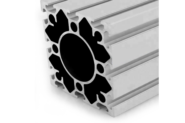
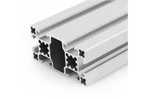
120 x 120 mm Aluminium Profile for Automotive Line Tooling
120 x 120 mm twelve-slot aluminium extrusion in 6063-T5 for welding jigs, assembly fixtures and robot pedestals. 9.40 kg/m, supplied cut and machined with locator faces flat to 0.1 mm per metre.
| Material | Aluminium |
|---|---|
| Alloy Grade | 6063-T5 |
| Temper | T5 |
| Section Size | 120 x 120 mm, twelve slots |
| Slot | 12 x 10.2 mm groove, 8 mm mouth, 40 mm pitch, outer pair 80 mm apart, M8 |
| Length | 6 m stock; cut to fixture list to +/-0.5 mm |
| Tolerance | EN 755-9, wall +/-0.15 mm; straightness 1.5 mm per metre; twist 2 degrees |
| Surface | Mill finish, or anodised AA15 to EN ISO 7599; clear or black |
| MOQ | 150 m |
| Lead Time | 24 to 34 days for cut and machined material, plus 6 to 9 days air freight |
| Loading Port | Shanghai / Ningbo |
| Supply Ability | 600 t per month extrusion with in-house machining and anodising |
| Payment Terms | T/T 30% deposit + 70% before shipment | L/C at sight |
| Trade Terms | FOB | CIF | DAP |
| Certifications | Mill certificate per heat, machining inspection report, coating thickness report, RoHS and REACH declarations |
01Why is repeatability set by the joint rather than the profile?
A 120 x 120 section at 9.40 kg/m has about 270 cm4 about its strong axis, which is roughly ten times a 40 x 40. Under the loads a fixture sees, the extrusion itself barely deflects. What moves is the joint: the connector, the bolt preload, the flatness of the mating face and the stiffness of whatever the fixture is bolted to.
That is why a fixture built from a stiff section can still repeat to only plus or minus 0.3 mm while an identical fixture on a properly anchored base repeats to 0.05 mm. The difference is not in the aluminium.
- Machine every face that carries a locator, a rail or a robot interface. An extruded face has a flatness of roughly 0.3 mm per metre and a twist of up to 2 degrees, which is not a datum.
- Use a connector that engages both slot flanges rather than a single central bolt. The load path is shorter and the joint is an order of magnitude stiffer in rotation.
- Anchor the base plate into the floor slab, not into a raised plinth that is itself flexible. Check the slab thickness before the design is fixed.
- Torque to a stated figure with a calibrated wrench, and record it. A fixture that is assembled by feel will not repeat after a rebuild.
02What does a 120 x 120 base actually do for a robot?
It raises the robot to a working height and it has to do that without becoming the compliant element in the system. Two numbers matter: static deflection at the tool centre point under the worst payload moment, and the first mode of the pedestal.
For a 1.2 m tall pedestal in 120 x 120, fixed at the base, the first bending mode is around 50 Hz on the estimated section properties. That is comfortably above the bandwidth of most position loops, which is why the pedestal is rarely the limiting element. The base plate and the anchor bolts usually are.
| Pedestal height | First mode, 120 x 120 | Comment |
|---|---|---|
| 0.6 m | about 200 Hz | Adequate for almost any application |
| 0.9 m | about 90 Hz | Adequate, check the base plate |
| 1.2 m | about 50 Hz | Still above typical loop bandwidth, base plate governs |
| 1.5 m | about 32 Hz | Approaching the range where the pedestal starts to matter |
| 1.8 m | about 22 Hz | Go up a section or brace the pedestal |
Calculated from the estimated 270 cm4 and 9.40 kg/m, treated as a cantilever fixed at the base. Real pedestals measure lower because the anchor detail is never perfectly rigid. Treat this as a screening table, then check the base plate.
03Should changeover be a locating pin or a whole fixture swap?
It depends on the changeover frequency and on what has to stay calibrated. A pin system keeps one frame and changes the tooling on top, which is fast and cheap but carries the pin wear into the repeatability budget. A whole fixture swap replaces the frame as well, which is slower and more expensive but takes the frame out of the repeatability chain entirely.
The practical break point is around one changeover per shift. Below that, pin systems win on cost. Above it, a second complete fixture usually pays back within a model year, because the line stops for minutes rather than hours.
Locating pin changeover
- One frame, several tooling sets
- Changeover in minutes
- Pin and bush wear enters the repeatability budget
- Needs a pin inspection interval in the maintenance plan
Whole fixture swap
- One frame per part variant
- Changeover in tens of minutes, but off line
- Frame taken out of the repeatability chain
- Higher capital, lower line downtime
04Which dimensions actually belong in a PPAP report?
Not every dimension on the drawing. A PPAP dimensional report is a demonstration that the process is capable on the characteristics that matter, and padding it with every extrusion dimension obscures that. Three groups are worth measuring on a fixture.
- Locator positions relative to the datum scheme. This is the characteristic that decides whether the part sits where the fixture says it does. Measure on a CMM, not with a tape.
- Locator face flatness and perpendicularity. A locator on a face that is 0.2 mm out of flat will produce a part that is 0.2 mm out, regardless of how well the pin fits.
- Frame squareness and the diagonal difference. Cheap to measure and it catches assembly errors that individual dimensions miss.
Extrusion dimensions such as wall thickness belong in the incoming inspection record, not in the PPAP report, unless the drawing calls them out as a characteristic. Mixing the two makes the report longer and the capability story weaker.
05Extrusion fixture or welded steel over three years?
The purchase price favours steel. The three year cost often favours aluminium, and the reason is not the material, it is the changeover and the rework.
| Cost line | Welded steel fixture | Extruded aluminium fixture |
|---|---|---|
| First cost | Lower per kilogram, lower fabrication labour | Higher per kilogram, but no welding and no painting |
| Lead time for a variant | 4 to 8 weeks with welding and stress relief | 1 to 2 weeks, cut and bolt |
| Changeover | Cut and re-weld, or build a second fixture | Unbolt and re-position on the slot pattern |
| Damage repair | Cut out and re-weld, then re-check alignment | Replace the affected member |
| Corrosion | Needs paint, and paint fails at weld toes | Anodised, no coating maintenance |
| Scrap value | Recyclable, low | Recyclable, higher per kilogram |
The honest caveat: aluminium is not the right answer for a fixture that sees heavy impact, or one that has to hold a preload for years at elevated temperature. Above about 100 C the temper starts to be a conversation, and welding aluminium in the field loses most of the strength in the heat affected zone. For a fixture that is bolted and kept at shop temperature, the aluminium case is usually clear.
06What five numbers should be on the enquiry?
The payload, the height, the locator tolerance, the changeover frequency and the floor. The floor is the one that gets forgotten and the one that decides whether the pedestal is the problem or the slab is.
- Payload and moment
- tool weight and the distance from the pedestal face, because the moment governs
- Pedestal height
- floor to robot interface, which sets the first mode
- Locator tolerance
- the repeatability the fixture has to hold, in mm
- Changeover frequency
- per shift or per week, which decides pin system against fixture swap
- Floor condition
- slab thickness and whether a plinth is involved
- Section
- 120 x 120 mm twelve slot at 9.40 kg/m, or 90 x 90 at 7.60 kg/m below 1 m
Send the payload, the height and the locator tolerance
- 120 x 120 mm, 6063-T5, twelve 10.2 mm slots, 9.40 kg/m
- 180 m cut to the fixture list, machined faces marked on the drawing
- Mill finish, or AA15 anodised for visible frames
- Locator faces to be machined flat within 0.1 mm per metre
- Floor slab detail attached
Machined faces are the item to settle early. A fixture drawing that asks for a locator on an as-extruded face will not hold the tolerance, and the fix is a machining step that has to be in the price from the start.
Related sections and categories
The 120 x 120 is the largest standard section in the 40 Series Aluminium Profiles range at a 40 mm slot pitch. Below it, the 40 x 120 mm eight slot section at 4.60 kg/m covers most mid-size fixtures, and the joint hardware is under joining plates.
Is a 120 x 120 aluminium pedestal stiff enough for a robot?
For pedestals up to about 1.2 m, yes. The first bending mode on the estimated section is around 50 Hz at 1.2 m, which is above the bandwidth of most position loops. Past 1.5 m the mode drops into the thirties and the pedestal starts to enter the control conversation. In practice the base plate and the anchor detail are the limiting elements well before the extrusion is.
Do I need to machine the faces, or can I bolt to the extrusion surface?
Machine any face that carries a locator, a rail or a robot interface. An as-extruded face has roughly 0.3 mm per metre flatness and up to 2 degrees of twist, which is not a datum. Faces that only carry a cover or a cable tray can stay as extruded. Settle this at enquiry, because the machining step has to be in the price.
What repeatability can an aluminium fixture actually hold?
Around plus or minus 0.05 mm is achievable with machined locator faces, a rigid base plate and a controlled torque on the joints. Without machined faces the same fixture will hold roughly plus or minus 0.3 mm. The difference is the machining and the anchor, not the section.
Can the frame be welded instead of bolted?
It can, but it should not be, for two reasons. Welding 6063-T5 costs 40 to 50 percent of the strength in the heat affected zone, and it removes the ability to re-position the frame on the slot pattern during a changeover. The bolted joint is what makes the system reconfigurable, and reconfigurability is the reason to use extrusion at all.
How long does a fixture frame take to supply?
24 to 34 days for cut, drilled and anodised material, plus 6 to 9 days air freight. If the section is in stock and the order is mill finish, 12 to 18 days is realistic. The machining of locator faces adds 3 to 5 days because it is a second operation after cutting.
Send the payload, the height and the locator tolerance
Give us the robot or tool weight, the pedestal height, the repeatability the fixture must hold and the floor slab detail. We will come back with the section, the machined faces and the joint hardware.
Request a quotationRelated Products
 45 x 90 mm Aluminium Profile: Stock Planning for Distributors
45 x 90 mm six-slot aluminium extrusion in 6063-T5 for distributor stock. 4.10 kg/m,…
 45 x 180 mm Aluminium Profile for Maghreb / EU-Bound Projects
45 × 180 mm aluminium extrusion in 6063-T5 for Maghreb fabricators feeding EU-bound projects.…
 45 x 180 mm Aluminium Profile for ESD-Safe Electronics Frames
45 × 180 mm aluminium extrusion in 6063-T5 for ESD-safe electronics frames sought by…
 45 x 180 mm Aluminium Extrusion vs Casting: Which One to Specify
45 × 180 mm aluminium extrusion in 6063-T5 as the worked example for extrusion…
 30 x 120 mm Aluminium Profile for Heavy Equipment Frames
30 x 120 mm ten-slot aluminium extrusion in 6063-T5 for construction equipment guards, platform…
 90 x 90 mm Aluminium Profile Supply: Stock Planning and Lead Time
90 x 90 mm eight-slot aluminium extrusion in 6063-T5 for multi-site supply across Maharashtra.…
 50 x 50 mm Aluminium Profile for Precision and Aerospace Fixtures
50 x 50 mm four-slot aluminium extrusion in 6063-T5 for inspection and assembly fixtures.…
 40 x 80 mm Aluminium Profile with 80 x 120 mm Beams: A Gantry Combination
Gantry pairing: 40 x 80 mm six-slot columns at 3.60 kg/m with an 80…
