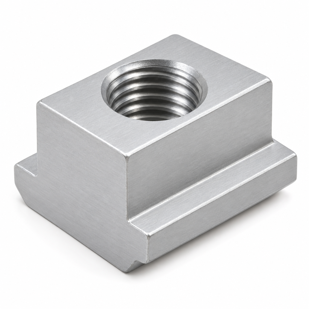
T-Slot Nut 50 Series M10 Hammer Nut for 50×50 Aluminium Extrusion
M10 hammer-head T-slot nut for the 10 mm groove of 50 x 50 mm and 60 mm aluminium extrusion, for column feet, base plates and machine mounts. Carbon steel zinc plated or 304 stainless, torque ceiling about 30 N m.
| Material | Carbon steel / 304 stainless steel |
|---|---|
| Alloy Grade | Grade 8.8 equivalent carbon steel / A2-70 stainless |
| Temper | custom |
| Section Size | M10, for 50 and 60 series 10 mm slot |
| Slot | Fits 10 mm slot mouth and 14 mm groove cavity of 50 and 60 series sections |
| Length | 20 mm body length along the slot |
| Tolerance | Thread to ISO 965-2 6H, head width -0.15 mm on the groove cavity |
| Surface | Zinc plated (clear trivalent) / passivated stainless |
| MOQ | 4000 |
| Lead Time | 16-26 days after deposit for zinc plated, 22-32 days for 304 |
| Loading Port | Shanghai / Ningbo |
| Supply Ability | 1.5 million pieces per month |
| Payment Terms | T/T 30% deposit + 70% before shipment | L/C at sight |
| Trade Terms | FOB | CIF | EXW |
| Certifications | ISO 9001:2015 | ISO 965-2 thread | RoHS | REACH |
Fastening elements · 50 series · M10
A 50 series T-slot nut is an M10 hammer-head nut for the 10 mm groove of a 50 x 50 mm aluminium extrusion. It is the fixing for the loaded joints of a heavy frame: column feet, base plates, gussets, guard posts and machine mounts, and it is also used on 60 series sections where the same 10 mm slot geometry appears. The body is about 20 mm long, weighs around 18 g in steel, and the thread is M10 x 1.5 ISO metric coarse with an empirical torque ceiling near 30 N m.
What changes at this size is not the strength of the screw but the behaviour of the joint. An M10 screw can develop enough preload to embed itself into the aluminium under the nut head, and once that happens the preload falls away and the joint starts to slide under load. So a heavy frame is not held by tightening harder — it is held by spreading the load over enough aluminium and by keeping the preload where it was set. Those two ideas govern everything below.
Where an M10 nut is the right grade
Fifty and sixty series frames are the load-bearing end of T-slot framing: machine bases, robot pedestals, mezzanine platforms, heavy guard structures and conveyor gantries. The 50 series and 60 series members are big, the joints carry real force, and the fixings are expected to stay tight for years without attention. An M10 nut in a 10 mm slot is the grade that matches that duty, and it is also the point at which the section starts to offer an alternative — the centre bore on these sections is large enough for a substantial through-bolt, which changes what the nut has to do.
The right way to think about it is that the nut provides a clamp and the clamp provides friction. Friction is what stops a bracket sliding, and it is proportional to the clamp load, which is proportional to the tightening torque. Anything that reduces the clamp load — a crushed lip, an embedded nut head, a stretched screw — reduces the friction, and the joint slips. On a light frame that is a nuisance; on a heavy frame it is the failure mode.
| Property | M10 50 series nut |
|---|---|
| Thread | M10 x 1.5 ISO metric coarse |
| Groove | 10 mm slot mouth, 14 mm cavity |
| Body length | 20 mm along the slot |
| Head thickness | 6 mm |
| Unit weight | approx. 18 g in steel |
| Torque ceiling | approx. 30 N m, empirical |
| Pull-out | approx. 3.5 to 5.0 kN per nut |
| Section pairing | 50 series and 60 series 10 mm slot sections |
Why a heavy joint starts to slide months after it was built
A joint that is tight when it is built can lose its preload in three ways, and at M10 torque all three are active. The first is embedment: the small peaks on the thread, under the screw head and on the nut head flatten under the clamp load, so the parts settle into each other and the screw loses a little of its stretch. The second is creep in the aluminium, which deforms slowly under a sustained pressure even when it is below yield. The third is thermal cycling, which alternately adds and removes load and slowly walks the joint towards the loose end of its range.
The result is a joint that passes inspection on day one and has lost a useful part of its clamp load by month three, which is why the slip shows up during production rather than at commissioning. It is also why a heavy frame benefits from being re-torqued once, after the first few weeks of running, when the embedment has finished and the joint has settled.
| Torque at the M10 screw | Condition of the joint |
|---|---|
| 10 to 15 N m | Secure for a static bracket, below the useful range for a loaded joint |
| about 30 N m | Design ceiling, full friction on both lips, no visible marking |
| 40 N m | Nut head embeds in the lip, preload begins to fall away |
| 50 N m and above | Local crush under the head, joint loses clamp load and slips |
Re-torque once, then leave it alone. On a heavy frame the first re-torque after a few weeks of running recovers the preload lost to embedment and is worth doing. Repeated tightening of the same joint does not add strength, it works the aluminium under the head and hastens the crush.
Three ways to stop the lip crushing under the head
The pressure under an M10 nut head is concentrated on the two lips of the slot, which on a 50 series section are around 2.5 mm thick. Spreading that pressure over more area, or moving the load off the lip altogether, is how the ceiling is raised without changing the section. Each of the three measures below does a different job and they can be combined.
Why big nuts should go in through the slot, not the end
A large nut can be fitted two ways: slid in from the open end of the member before it is closed, or inserted through the slot mouth from the side and rotated into position. On a light frame the slide-in type is the economical choice. On a heavy frame the calculation reverses, and the reason is the cost of being wrong rather than the cost of the nut.
Heavy frames are built in a fixed order. The columns go up, the base plates and gussets are fitted, the beams are dropped in and the corner joints are closed. By the time the frame is square, most member ends are covered by a plate, a foot or another member, and there is no open end left for a slide-in nut. If the drawing changes at that point — a guard post moves, a cable tray is added, a sensor bracket appears — a slide-in nut means opening a loaded corner, and on a heavy frame that means supporting the frame while it is done. A side-entry nut costs a little more per piece and removes that risk entirely.
- Decide the entry type at the design stage Mark on the frame drawing which faces will ever carry a new bracket after the frame is built. Those faces get side-entry nuts; the faces that are fixed for good can use the slide-in type. This is a drawing note, not a purchasing decision made after the fact.
- Plan the assembly order around the fixings Slide-in nuts have to be in position before the end is closed, so they appear in the assembly sequence before the corner plates. Side-entry nuts can be fitted at any point, which lets the frame be built and squared first and the accessories added afterwards.
- Keep access to the slot face A side-entry nut needs a clear run at the slot mouth. Where a panel or a cover will sit flush over the slot, leave a gap or a removable section, or fit the nut before the panel. Access decided at the design stage is free; access discovered as missing on site is a rework order.
- Allow for one late change per frame In practice every heavy frame gets one accessory that was not on the drawing. Carrying a small stock of side-entry M10 nuts on site turns that change from a day of dismantling into ten minutes of work, and the cost of the stock is trivial against the cost of the delay.
Material and finish for a heavy frame
Carbon steel zinc plated is the standard and is right for indoor machine framing, where the thread is hard and the plating is not challenged. 304 stainless is specified for outdoor platforms, washdown areas and food or pharmaceutical installations, and 316 where chlorides or chemicals are present. Both stainless grades are softer than plated carbon steel, so at 30 N m the nut thread is the weaker element and the ceiling should be treated as slightly lower.
Where a heavy frame is exposed and loaded at the same time, the galvanic pair between a stainless nut and an aluminium slot is worth a thought: a dry joint is fine for years, a wet one attacks the aluminium around the nut first, which on a loaded joint is a slow loss of bearing area. A plated screw with a stainless nut, or a barrier washer between the metals, is the usual answer.
Ordering the M10 50 series nut
We supply the M10 nut in carbon steel zinc plated and in 304 stainless, with a 20 mm body as standard, in both the slide-in form and the side-entry form. It is made for the 10 mm groove of the 50 series aluminium profiles and the 60 series aluminium profiles. The minimum order is 4,000 pieces per material and type, and the two entry types and the two materials can be combined in one order for pricing. At this size the part is machined rather than cold formed, so the price is dominated by material and by the threading operation, and the volume discount is flatter than it is on a small nut.
Lead time is 16 to 26 days after deposit for zinc plated and 22 to 32 days for stainless. Terms are FOB, CIF or EXW from Shanghai or Ningbo, with T/T 30 % deposit and the balance before shipment, or an L/C at sight. OEM and ODM are available: we mark the head with your part number, form a flange or washer face on the head to spread the load, and produce a special body length where a joint needs a longer engagement than the standard 20 mm.
Frequently asked questions
What torque should an M10 T-slot nut be tightened to?
About 30 N m as an empirical ceiling, above which the nut head starts to embed in the aluminium lip and the joint loses preload. It depends on the section and on how much of the body is engaged, so check a sample joint before setting a wrench for production.
Why has my heavy frame joint started to slip?
Almost always because the preload has fallen away rather than because the fixing has failed. Embedment under the nut head, creep in the aluminium and thermal cycling all reduce the clamp load over months, and once the friction is gone the bracket slides. Re-torque once after the first few weeks, then leave the joint alone.
How do I stop the slot lip crushing under a heavy load?
Spread the pressure over more aluminium or move the load off the lip. A hardened washer or a wide bracket foot lowers the pressure under the head, a full 20 mm body spreads it along the slot, and where the joint does not need to be adjustable a through-bolt in the centre bore takes the load out of the lip altogether.
Should I use a slide-in nut or a side-entry nut on a heavy frame?
Side entry for any face that might carry a fixing added after the frame is built. A slide-in nut has to be in place before the member end is closed, and opening a loaded corner to fit one is a support-and-dismantle job. The price difference between the two types is small against the cost of that rework.
What is the minimum order and lead time?
4,000 pieces per material and type, with entry types and materials combined in one order for pricing. Lead time is 16 to 26 days after deposit for zinc plated and 22 to 32 days for stainless, on FOB, CIF or EXW terms with T/T or L/C payment.
Send the frame drawing and the joints that carry load
Mark the joints that carry the machine load and the faces that might get a new bracket after build, and we will quote the right mix of slide-in and side-entry M10 nuts, with the flange head or the through-bolt recommendation where the lip is under pressure. Send the material, the quantity and the torque you intend to use, and we will return unit pricing and the FOB lead time.
Request a QuoteRelated Products
 T-Nut and Bolt Set Aluminium Profile Fastener Kit M5 M6 M8 20-40 mm T-Slot Hardware
Matched T-nut, bolt and washer set for aluminium profile frames in M5, M6 and…
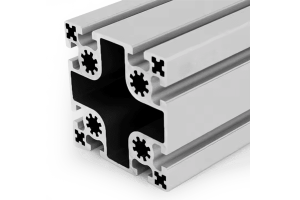 PG50 100×100 mm Eight Slot Aluminium Strut Profile for Heavy Machine Columns
A 100 x 100 mm eight slot PG50 aluminium strut profile with two slots…
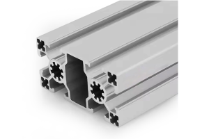 PG50 100×50 mm Six Slot Aluminium Strut Profile Rectangular Machine Beam
A 100 x 50 mm six slot PG50 aluminium strut profile with slots on…
Aluminium Profile Truck Body Frame 50 x 100 mm for Dry Freight Boxes
50 x 100 mm six slot aluminium profile at about 5.40 kg/m for dry…
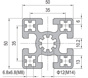 50 x 50 mm Aluminium Profile for Precision and Aerospace Fixtures
50 x 50 mm four-slot aluminium extrusion in 6063-T5 for inspection and assembly fixtures.…
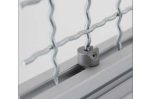 Panel Mounting Nut Block
Block that seats in the profile slot and provides a captive threaded hole at…
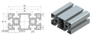 Strut Aluminium Profile 50×100 mm 2-Slot Heavy T-Slot Beam Extrusion
50 x 100 mm heavy two-slot T-slot strut aluminium beam in 6063-T5, about 6.2…
50 x 50 mm Four Slot Aluminium Strut Profile Heavy Frame Cross Member
50 x 50 mm four slot T-slot strut aluminium profile in 6063-T5, about 3.1…
