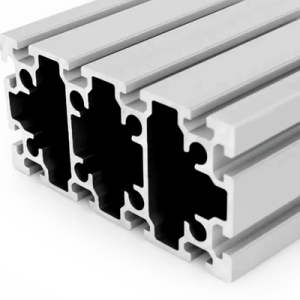
PG30 120 x 60 mm Twelve Slot Aluminium Strut Profile Heavy Frame Beam
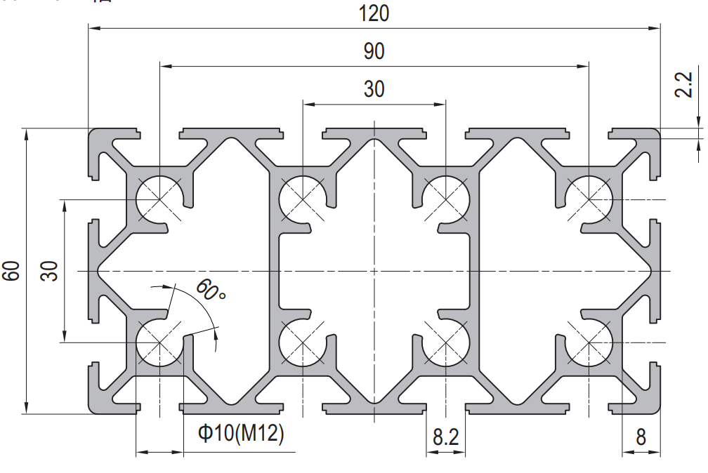
A 120 x 60 mm twelve slot PG30 aluminium strut profile at about 5.20 kg/m with 8.2 mm grooves on a 30 mm pitch and the outer pair 90 mm apart. Butt, corner, tee and offset joints on one member.
| Material | Aluminium |
|---|---|
| Alloy Grade | 6063-T5 |
| Temper | T5 |
| Section Size | 120 x 60 mm |
| Slot | 12 x 8.2 mm groove, 6 mm mouth, 30 mm pitch, outer pair 90 mm apart, M8 |
| Length | 6 m stock, cut to drawing to +/-0.5 mm |
| Tolerance | EN 755-9 / GB/T 6892, wall +/-0.15 mm |
| Surface | Mill finish / clear anodised / black anodised |
| MOQ | 200 m |
| Lead Time | Typically 20 to 30 days after deposit for mill finish |
| Loading Port | Shanghai, Ningbo, Qingdao |
| Supply Ability | Extrusion, cutting, machining and anodising in house |
| Payment Terms | T/T 30 per cent deposit, balance against copy of bill of lading; L/C at sight for larger orders |
| Trade Terms | FOB, CIF, CFR, EXW |
| Certifications | ISO 9001:2015, EN 755-9, RoHS and REACH declarations |
01What is the 120 x 60 mm twelve slot profile?
How are the twelve slots arranged?
Four on each 120 mm face and two on each 60 mm face, all at 30 mm centres, with the outer pair on the wide faces 90 mm apart. That gives four fixing lines across the width and two across the depth, which is what makes this the most joint-friendly section in the 30 series.
What is it used for?
Press frames, heavy machine bases, large enclosure frames, gantry uprights and any structure where a single member has to accept several different joint types along its length. At about 5.20 kg/m a 6 m bar is roughly 31 kg, so it is a two-person member.
Why twelve slots rather than eight?
Because a heavy frame member is a junction, not just a beam. At any point along it something else may need to meet it end on, at right angles, at a tee, or offset. Each of those joints wants a different set of grooves, and with twelve available none of them have to fight for the same one.
02Section data
| Item | Value | Note |
|---|---|---|
| Envelope | 120 x 60 mm | rectangular, heavy section |
| Slots | 12 | 8.2 mm groove, 6 mm mouth |
| Slot layout | 4 per 120 mm face, 2 per 60 mm face | as drawn |
| Slot pitch | 30 mm | the 30 series module |
| Outer pair | 90 mm apart | across the wide face |
| Fastener | M8 | 30 series slot nuts |
| Weight | approx. 5.20 kg/m | a 6 m bar is about 31 kg |
| Alloy | 6063-T5 | EN AW-6063 |
| Standard | EN 755-9 / GB/T 6892 | wall tolerance +/-0.15 mm |
| Length | 6 m stock | cut to drawing to +/-0.5 mm |
The two grooves on each 60 mm face are the detail worth noticing. They are what lets a member join the narrow side of this beam without an adapter plate, and they are the reason this section gets used as a frame node rather than a plain beam.
03Four joint types, and which slots each one uses
This is the whole argument for the section. On a four slot member, every joint competes for the same grooves and anything beyond a simple corner needs a machined plate. On a twelve slot member each joint type gets its own set, and the frame can be assembled from standard parts.
The four joints below are the ones that come up on almost every heavy frame. Read the slot column as the set of grooves the joint consumes: if two joints on the same piece of the beam want the same groove, you have a clash and something has to move.
| Joint type | What it does | Which slots it uses | Notes |
|---|---|---|---|
| Butt | joins two members end to end along one axis | the two inner grooves on one wide face, plus the centre bore if present | the strongest end joint; the load stays on the axis |
| Corner | joins two members at 90 degrees at a frame corner | one outer groove on the wide face and one groove on the adjacent narrow face | use the outer groove: it sits over a web |
| Tee | joins the end of one member into the side of another | one inner groove on a wide face for the bracket, and the outer pair for the clamp | the classic place where a four slot section runs out of grooves |
| Offset | joins two members whose axes do not meet | the outer pair on a wide face, 90 mm apart | the 90 mm spread is what lets an offset joint resist its own moment |
The offset joint is the one that justifies the section on its own. Two members whose centrelines do not meet apply a moment to the joint, and the only way to resist that moment with standard parts is to spread the fixing across two grooves. At 90 mm apart, the outer pair does exactly that. On a four slot member the same joint needs a fabricated plate.
The tee joint is the second one. It wants a bracket in one groove and a clamp across two more, which is three grooves at one point. A four slot member has them, but they are then all used and nothing else can be fixed anywhere near that joint.
04Planning the slots before you cut
The way this goes wrong on site is that the beam is cut, delivered and fitted, and then someone finds that the sensor bracket and the corner bracket want the same groove. With twelve grooves that is a planning failure, not a section limitation.
The fix is a slot plan: a single drawing of the member with every joint, bracket and service marked and the groove it uses named. It takes an hour and it removes the whole class of problem.
Slot plan for a 120 x 60 member
- Mark every joint position along the member first, before anything else.
- Assign each joint its groove set from the table above.
- Check for clashes: two joints wanting the same groove at the same point.
- Assign services to a groove that no joint uses.
- Reserve at least one groove as spare along the full length.
- Mark the cut length and the end preparation on the same drawing.
- Send the slot plan with the enquiry: it is what makes the quote accurate.
If a clash is unavoidable, the options in order of cost are: move one joint along the member, use a bracket that reaches two grooves instead of one, or machine an adapter plate. Machining is the expensive one and it is almost always avoidable on this section.
05Failure modes to design out
| What goes wrong | Why it happens | Design it out by |
|---|---|---|
| Two joints want the same groove | no slot plan was made before cutting | draw the slot plan and resolve clashes on paper, not on site |
| Offset joint rotates | it was fixed in one groove instead of the outer pair | use the outer pair, 90 mm apart, so the joint resists its own moment |
| Corner bracket pulls out | it was fixed in a mid-face groove with no web behind it | use an outer groove over a web |
| Beam twists under an off-centre load | the load was applied outside the outer groove | keep loads inboard of the outermost grooves, or add a stay |
| Wrong series accessories arrive | the order said 120 x 60 and not 30 series | quote the accessory list as a 30 series kit |
06What to check before you order
Procurement checklist for the 120 x 60 mm twelve slot section
- Confirm the series: 30 series is an 8.2 mm groove with a 6 mm mouth on a 30 mm pitch, M8.
- Confirm the joint types the member has to accept, and send the slot plan.
- Confirm the outer pair spread is what your offset joints need: 90 mm.
- Confirm the cut list with lengths and end preparation.
- Confirm the handling plan: a 6 m bar is about 31 kg.
- Confirm the accessory list as a 30 series kit: M8 slot nuts, corner and tee brackets, cover strips, end caps.
- Confirm the finish and the quantity in metres.
07Terms used on this page
- Butt joint
- Two members joined end to end along one axis. The load stays on the axis, so it is the strongest of the four.
- Corner joint
- Two members joined at 90 degrees at a frame corner.
- Tee joint
- The end of one member meeting the side of another. It wants three grooves at one point.
- Offset joint
- A joint where the two members’ axes do not meet, so the joint has to resist a moment. It needs two grooves spread apart.
- Outer pair
- The two grooves furthest apart on the wide face, here 90 mm apart. They sit over the webs and resist moment.
- Slot plan
- A drawing of a member with every joint, bracket and service assigned to a named groove.
08Questions buyers ask
How are the twelve slots arranged?
Four on each 120 mm face and two on each 60 mm face, all at 30 mm centres, with the outer pair on the wide faces 90 mm apart.
Why choose this over a smaller section?
When one member has to accept several joint types along its length. Twelve grooves lets butt, corner, tee and offset joints coexist without a machined adapter plate.
What is the weight per metre?
Approximately 5.20 kg/m, so a 6 m stock length is about 31 kg.
What is the outer pair spread?
90 mm, which is what lets an offset joint resist its own moment with standard parts.
Is 30 series compatible with 40 series?
No. The mouth is 6 mm against 8 mm and the pitch is 30 mm against 40 mm, so the slot nuts and brackets do not interchange.
Can it be supplied cut and machined to a slot plan?
Yes. Send the cut list and the slot plan with the tap positions and the lengths arrive ready to assemble.
What we need to quote this section
- The section reference and the series, stated explicitly.
- The cut list with lengths and end preparation.
- The slot plan: which joints go where and which grooves they use.
- Any tapping required, and the engagement length.
- The accessory list as a 30 series kit, including corner and tee brackets.
- The finish and the quantity in metres.
Quotations are broken out into extrusion, cutting, machining, finish and hardware, so you can see which step is driving the cost. Browse the full aluminium profile catalogue and the 30 series aluminium profiles range for related sections.
Building a heavy frame with several joint types?
Send the cut list and the slot plan. We quote extrusion, machining, finish and the 30 series hardware as separate lines.
Request a quotationRelated Products
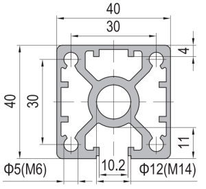 PG40 40 x 40 mm Single Slot Aluminium Strut Profile Guide Rail Base
40 x 40 mm single-slot aluminium strut profile with one 10.2 mm groove on…
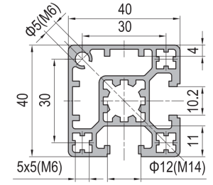 PG40 40 x 40 mm Two Slot Type A Aluminium Strut Profile Guide Rail
40 x 40 mm Type A two slot asymmetric PG40 aluminium strut profile in…
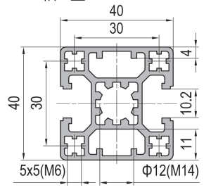 PG40 40 x 40 mm Two Slot Type B Aluminium Strut Profile Opposite Rail
40 x 40 mm Type B two-slot aluminium strut profile with two 10.2 mm…
 PG40 40 x 40 mm Four Slot Heavy Aluminium Strut Profile Standard Frame
40 x 40 mm heavy-wall four-slot aluminium strut profile with 10.2 mm grooves, 8…
 PG40 40×40 mm Four Slot Light Wall Aluminium Strut Profile Cost Optimised T-Slot Extrusion
40 x 40 mm four slot light wall PG40 aluminium strut profile in 6063-T5…
 PG40 40×40 mm R90 Quarter Round Aluminium Strut Profile Radius Corner Guard Frame Extrusion
40 x 40 mm R90 quarter round PG40 aluminium strut profile in 6063-T5 with…
 PG40 200 x 80 mm Fourteen Slot Aluminium Strut Profile Large Section Beam
A 200 x 80 mm fourteen slot PG40 aluminium strut profile at about 7.80…
 PG45 180 x 90 mm Twelve Slot Aluminium Strut Profile Heavy Duty Column
A 180 x 90 mm twelve slot PG45 aluminium strut profile at about 9.50…
