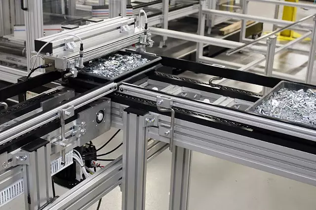
Conveyor System Aluminium Profile Extrusion Frame 45×60 mm for Belt and Roller Lines
A bolted conveyor frame in 45 x 60 mm T-slot aluminium profile with 45 x 45 mm legs and cross members. Sized on deflection at span divided by 1000 for belt tracking.
| Material | Aluminium |
|---|---|
| Alloy Grade | 6063-T5 |
| Temper | T5 |
| Section Size | 45 x 60 mm side rail, 45 x 45 mm leg |
| Slot | 10 mm groove, M8 and M10 slot nuts, 45 mm pitch |
| Length | 6 m stock, cut to a line cutting list to +/-0.5 mm |
| Tolerance | EN 755-9 / GB/T 6892, wall +/-0.15 mm |
| Surface | Mill finish / clear anodised / black anodised |
| MOQ | 100 |
| Lead Time | 20-30 days after deposit for mill finish |
| Loading Port | Shanghai / Ningbo |
| Supply Ability | 300 t per month |
| Payment Terms | T/T 30% deposit + 70% before shipment | L/C at sight |
| Trade Terms | FOB | CIF | EXW |
| Certifications | ISO 9001:2015 | EN 755-9 | RoHS | REACH |
Framing systems · Conveyor and transfer lines
A conveyor system aluminium profile frame is a bolted structure built from 45 x 60 mm four slot T-slot extrusion for the side rails, with 45 x 45 mm legs and cross members. The 45 x 60 mm section weighs about 3.3 kg/m and gives roughly 31 cm4 on the 60 mm axis and 21 cm4 on the 45 mm axis, so it is always mounted with the 60 mm dimension vertical. For heavier lines the same node family runs up to 180 x 90 mm at about 9.5 kg/m.
A conveyor frame looks like a static machine frame with rollers on top, but it is not the same structure at all. A static frame is loaded once and then left alone, so it is designed against yield — does anything break. A conveyor frame carries a reversing load millions of times, and it is designed against deflection and against the joint coming loose. Those are two different calculations, and the second one is where most conveyor frames actually fail.
A conveyor is a fatigue structure
Every revolution of a roller, every pass of a belt splice and every product transfer puts a load cycle into the frame. A line running 16 hours a day at 30 m/min with a 500 mm roller pitch sees about 57,000 roller rotations per hour, and each one loads and unloads the side rail. Over a year that is tens of millions of cycles. No static frame experiences anything like it.
Aluminium does not have an endurance limit the way steel does — its fatigue strength keeps falling as the cycle count rises rather than flattening out. For 6063-T5 extrusion the practical design stress for a high-cycle application is a small fraction of the yield strength, and the consequence is that the frame has to be sized so the alternating stress is low. In practice that means sizing on deflection, because a frame stiff enough to hold its shape is automatically well below the fatigue stress.
| Design question | Static machine frame | Conveyor frame |
|---|---|---|
| Governing criterion | Yield strength | Deflection and fatigue |
| Load character | Static or occasional | Reversing, millions of cycles |
| Deflection limit | L / 200 to L / 500 | L / 1000 or tighter at pulley centres |
| Joint concern | Static strength | Preload retention over time |
| Failure mode | Deformation or breakage | Loosening, then misalignment |
| Re-torque needed | Usually not | After 100 h and again after 500 h |
The frame does not have to break to stop the line. The commonest conveyor failure is a rail that has sagged or a joint that has slipped, so the belt no longer tracks. Neither of those is a strength failure, and neither shows up in a static stress check.
Size the side rail on deflection, not on stress
The side rail has to hold the pulley centres and the roller pitch within tolerance, because belt tracking is controlled by the relationship between the two pulleys. A useful working limit is a deflection of about 1 mm per metre of span, which is span divided by 1000. Working backwards from that limit gives the second moment of area the rail needs, and that number is the design. The table below assumes a combined belt, roller and product load of 0.5 N/mm, which is roughly 50 kg per metre of conveyor.
| Support span | Required second moment of area at L / 1000 | Rail to use | Verdict |
|---|---|---|---|
| 1.0 m | 9.3 cm4 | 45 x 45 mm four slot (15.5 cm4) | Comfortable |
| 1.2 m | 16.1 cm4 | 45 x 45 mm heavy (19.5 cm4) | Passes |
| 1.5 m | 31.4 cm4 | 45 x 60 mm on edge (31 cm4) | Right at the limit — use 60 x 60 heavy (38 cm4) if in doubt |
| 2.0 m | 74.4 cm4 | No 45 mm section will do it | Add a support leg or step up to a deeper section |
Two things follow from that table. First, a belt conveyor needs a support leg roughly every 1.5 m — the span, not the section, is what decides whether the rail is stiff enough. Second, the 60 mm dimension has to be vertical. Laid flat the same rail uses only its 21 cm4 figure and the achievable span drops by about a third. Getting the orientation wrong is the single most expensive mistake on a conveyor frame, because it is invisible until the belt starts tracking badly.
The bolt is not the weak link — the slot is
This is the point that decides how a conveyor frame should be jointed, and it is routinely missed. An M8 grade 8.8 bolt has a tensile capacity of the order of 15 kN. But an M8 hammer-head T-slot nut in an 8 mm groove of a 40 series profile pulls out of the slot at around 1.5 to 2.2 kN per nut in a standard section. The bolt is seven times stronger than the slot it is anchored in.
So the capacity of a T-slot joint is set by the slot, and the tightening torque ceiling is correspondingly low — about 15 N m for an M8 nut in a 40 or 45 series slot, and about 30 N m for an M10 nut in a 50 series slot. Over-torquing does not make the joint stronger; it deforms the slot lip and makes it weaker.
| Fastener and slot | Slot pull-out per nut | Torque ceiling | What it means for a conveyor |
|---|---|---|---|
| M8 nut in a 40 series 8 mm groove | approx. 1.5 to 2.2 kN | approx. 15 N m | Use four or more nuts where a rail is loaded in tension. |
| M8 nut in a 45 series 10 mm groove | higher than 40 series, same torque | approx. 15 N m | The deeper groove helps, but the torque ceiling does not change. |
| M10 nut in a 50 series 10 mm groove | approx. 3.5 to 5.0 kN | approx. 30 N m | The right choice for legs and base plates on a heavy line. |
| End face connection into the core bore | set by the bolt, not the slot | by thread size | Use where a member is pulled, not pushed. |
The practical rule for a conveyor frame is therefore: wherever a member is loaded in tension — a leg hanging under a rail, a pulley mount, a drive reaction — do not rely on the slot alone. Use an end-face connection into the profile’s core bore, a joining plate, or an anchor connector, all of which transfer the load into the section rather than into the slot lip. Keep the slot connections for members in shear and for brackets, and use more of them than the load strictly needs. The joining plates and anchor connectors ranges cover both cases.
Keeping a bolted frame tight on a running line
- Torque to the slot ceiling, not to the bolt rating An M8 bolt can take far more torque than the slot can. Use the nut’s ceiling — about 15 N m for M8 in a 40 or 45 series slot — and use a torque wrench rather than feel.
- Use the largest washer face the slot allows A formed flange or a hardened washer spreads the clamping load over more of the slot lip, which is what the joint is actually limited by.
- Use anti-torsion nuts where the load is one-sided A nut that can rotate in the slot will rotate under vibration. A serrated or ribbed nut body locks against the slot wall and holds its position.
- Re-torque after the first 100 hours, then again at 500 Most preload loss happens in the first weeks of running. A scheduled re-torque catches it before it becomes a tracking problem.
- Check the frame for squareness, not just for tightness A conveyor frame can be perfectly tight and still be out of square. Measure the diagonals of each bay at commissioning and record them so you have a baseline to compare against.
Frequently asked questions
Why not weld the conveyor frame?
Welding distorts the rail, so the pulley centres move and the belt will not track. It also destroys the temper in the heat affected zone, dropping the strength in the weld area to around 60 per cent of the parent metal. A bolted frame is straight off the saw and can be adjusted after installation.
What support spacing do you recommend?
About 1.5 m for a 45 x 60 mm rail at 50 kg per metre of load, which is the span divided by 1000 limit. Halve that spacing if the conveyor carries a heavy product or if the belt tension is high.
Can the frame be extended later?
Yes. Cut a new section and bolt it into the existing leg positions, or add a leg and extend. Keep the belt tensioning arrangement at the drive end so an extension does not disturb the take-up.
Should I use stainless fasteners?
In a wash-down, food or wet environment, yes — A2 or A4 stainless throughout. In a dry general-purpose line, zinc plated steel is adequate and cheaper, but do not mix steel and stainless in the same joint.
Do you supply the frame assembled or as lengths?
As cut lengths with hardware, or as pre-assembled bays for large orders. Tell us the line layout, the belt width, the product weight and the support spacing and we will quote either option.
Send the line layout and the belt data
Tell us the conveyor length, belt width, product weight and belt tension. We will size the side rail and the support spacing, specify the joint types and quote the frame as cut lengths or as pre-assembled bays.
Request a QuoteRelated Products
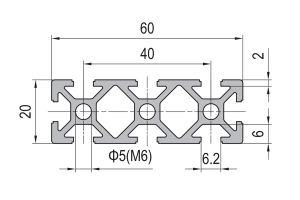 PG20 60 x 20 mm Eight Slot Aluminium Strut Profile Wide Miniature Rail
60 x 20 mm eight-slot aluminium strut profile with 6.2 mm grooves on a…
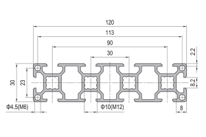 PG30 120 x 30 mm Ten Slot Aluminium Strut Profile Wide Multi Slot Rail
A 120 x 30 mm ten slot PG30 aluminium strut profile wide beam with…
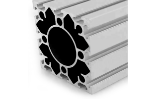 PG40 120×120 mm Twelve Slot Aluminium Strut Profile with 62 mm Centre Bore
A 120 x 120 mm twelve slot PG40 aluminium strut profile with a 62…
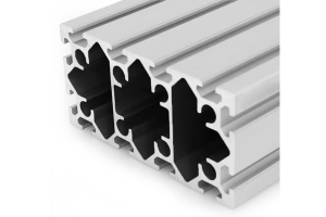 PG40 160×80 mm Twelve Slot Aluminium Strut Profile Heavy Beam for Gantry Frames
A 160 x 80 mm twelve slot PG40 aluminium strut profile heavy beam with…
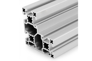 PG40 80×80 mm L-Shape Eight Slot Aluminium Strut Profile Corner Section
An 80 x 80 mm L-shape eight slot PG40 aluminium strut profile corner section…
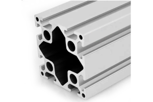 PG40 80×80 mm Eight Slot Heavy Aluminium Strut Profile High Load Column
An 80 x 80 mm eight slot heavy PG40 aluminium strut profile with diamond…
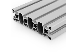 PG40 160×40 mm Ten Slot Aluminium Strut Profile Wide Beam for Overhead Rails
A 160 x 40 mm ten slot PG40 aluminium strut profile wide beam with…
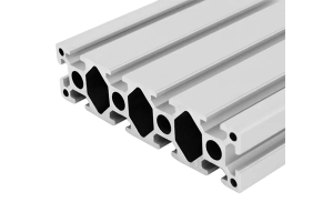 PG40 160×40 mm Ten Slot Heavy Aluminium Strut Profile for Cantilever Arms
A 160 x 40 mm ten slot heavy PG40 aluminium strut profile with round…
