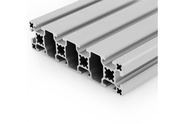
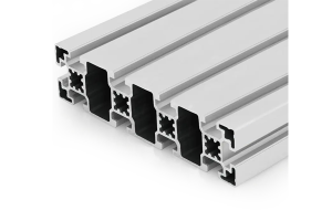
PG40 160×40 mm Ten Slot Aluminium Strut Profile Wide Beam for Overhead Rails
A 160 x 40 mm ten slot PG40 aluminium strut profile wide beam with 10.2 mm grooves and square M6 corner holes. For overhead rails, cantilever arms and wide machine beams.
| Material | Aluminium |
|---|---|
| Alloy Grade | 6063-T5 |
| Temper | T5 |
| Section Size | 160 x 40 mm |
| Slot | 10 x 10.2 mm groove, 8 mm mouth, 40 mm pitch, outer pair 120 mm apart, M8 |
| Length | 6 m stock, cut to drawing to +/-0.5 mm |
| Tolerance | EN 755-9 / GB/T 6892, wall +/-0.15 mm |
| Surface | Mill finish / clear anodised / black anodised |
| MOQ | 150 |
| Lead Time | 20-30 days after deposit for mill finish |
| Loading Port | Shanghai / Ningbo |
| Supply Ability | 250 t per month |
| Payment Terms | T/T 30% deposit + 70% before shipment | L/C at sight |
| Trade Terms | FOB | CIF | EXW |
| Certifications | ISO 9001:2015 | EN 755-9 | RoHS | REACH |
Structural framing · PG40 wide beam
A PG40 160 x 40 mm ten slot aluminium strut profile is a wide flat beam with a 40 mm slot pitch, a 10.2 mm groove and an 8 mm slot mouth, taking 40 series M8 hardware. The outer slots on the 160 mm face are 120 mm apart, the corner holes are 5 x 5 mm tapped M6 and the Ø12 mm bore is tapped M14. The flange is 4 mm and the web 11 mm, and the section weighs about 5.8 kg/m. It is supplied in 6063-T5, cut and machined to order.
The question this section always raises is what the extra 40 mm of depth is worth compared with a 120 x 40 mm beam in the same range. The answer is about 2.4 times the stiffness for about 26 per cent more weight, which is a good trade — but only if you mount it the right way up. A 160 x 40 mm section laid flat is softer than a 120 x 40 mm section on edge, so the orientation decision comes before the size decision.
What the extra 40 mm of depth buys
Stiffness in bending goes with the cube of the depth, so increasing the depth from 120 mm to 160 mm is a 33 per cent increase in a dimension that is cubed. The result is a disproportionate gain, and the table below sets it against the weight penalty.
| Section, mounted on edge | Depth | Second moment of area | Weight | Deflection under the same load |
|---|---|---|---|---|
| 120 x 40 mm ten slot | 120 mm | approx. 220 cm4 | approx. 4.60 kg/m | Reference |
| 160 x 40 mm ten slot | 160 mm | approx. 540 cm4 | approx. 5.80 kg/m | About 41 per cent of the reference |
Read the last column carefully. The 160 x 40 mm beam deflects about 41 per cent as much as the 120 x 40 mm beam — in other words it is roughly 2.4 times as stiff — for 26 per cent more weight. That is the whole argument for the larger section, and it is a strong one, because 2.4 times the stiffness for 1.26 times the weight is a much better exchange rate than adding wall thickness can ever give you.
Depth beats wall thickness, always. If you need more stiffness and you have room for a deeper section, go deeper. Adding wall thickness to a section of the same depth buys a fraction of what adding depth does, at a similar weight penalty.
Mount it deep, not flat
A 160 x 40 mm section is a wide beam, and the temptation on an overhead rail is to lay it flat so there is a broad top surface for a trolley or a carriage to run on. Structurally that is the worst thing you can do, because it puts the 40 mm dimension in the load direction instead of the 160 mm one.
The stiffness of the section is proportional to the width times the cube of the depth, so swapping the two dimensions changes the second moment of area by the ratio of their squares: 160 squared over 40 squared is 16. Laid flat the same section is about sixteen times softer than it is on edge, which is not a tuning difference, it is a different structure.
| Orientation | Depth in the load direction | Relative stiffness |
|---|---|---|
| On edge, 160 mm vertical | 160 mm | Reference, the stiff direction |
| Laid flat, 40 mm vertical | 40 mm | About one sixteenth of the reference |
Sizing an overhead rail
- Fix the deflection limit from the process A manual push trolley and a powered carriage with a position sensor have very different tolerances. The limit comes from what runs on the rail.
- Calculate the required second moment of area For a central point load on a simply supported beam, the deflection is the load times the cube of the span divided by 48 times the modulus times the second moment of area. Solve for the second moment of area.
- Check the answer against 540 cm4 At a span of 2 m and a 5 kN central load this section gives about 2.2 mm, which is inside an L/500 limit. Beyond about 2.5 m at that load you need a mid support or a deeper beam.
- Use the M14 bore for the rail supports The rail hangers carry the whole load. Fix them into the Ø12 mm bores tapped M14 rather than the slots, and space them on the calculated span.
- Check the rail for twist as well as sag An overhead rail that is loaded off-centre twists as well as bends. A single beam on edge has limited torsional stiffness, so a pair of rails or a box arrangement is better for a heavy off-centre carriage.
Frequently asked questions
Should I use the 160 x 40 mm or the 120 x 40 mm section?
Compare the required second moment of area with 540 cm4 and 220 cm4. If the job needs more than about 220 cm4, the 160 mm section is the cheaper way to get there than any increase in wall thickness.
Can I mount it flat to give a wider running surface?
You can, but the section will be about sixteen times softer, so it will sag badly over any real span. Mount it on edge and fit a separate track or wear strip if a carriage has to run on it.
What is the maximum span?
At a 5 kN central load and an L/500 limit, about 2.5 m. Send us the span, the load and the tolerance and we will calculate it for this section.
What is the difference between this and the heavy version?
Internal wall thickness and the corner hole form. The heavy version has round M6 corner holes instead of square ones, which gives a better thread and easier chip clearing for tapped connections.
Do you supply it cut and drilled?
Yes. We cut to your cutting list to plus or minus 0.5 mm, face and square the ends, drill and tap the corner holes and the M14 bore, and supply end caps.
Send the rail span and the mounting orientation
Tell us the span, the load, the deflection limit and which dimension stays vertical. We will confirm whether the 160 x 40 mm section is right and quote cut lengths and machining.
Request a QuoteRelated Products
 PG40 160×40 mm Ten Slot Heavy Aluminium Strut Profile for Cantilever Arms
A 160 x 40 mm ten slot heavy PG40 aluminium strut profile with round…
 PG40 120×40 mm Eight Slot Aluminium Strut Profile Standard Beam for Table Frames
A 120 x 40 mm eight slot PG40 aluminium strut profile standard beam with…
 PG40 120×40 mm Eight Slot Heavy Aluminium Strut Profile for Machine Bases
A 120 x 40 mm eight slot heavy PG40 aluminium strut profile with round…
 PG40 80×40 mm Six Slot Super Light Aluminium Strut Profile for Enclosures
An 80 x 40 mm six slot super light PG40 aluminium strut profile with…
 PG45 90×90 mm Eight Slot Aluminium Strut Profile M10 Column Section
A 90 x 90 mm eight slot PG45 aluminium strut profile with 8 x…
 PG45 90×90 mm Eight Slot Heavy Aluminium Strut Profile for Heavy Machinery Frames
A 90 x 90 mm eight slot heavy PG45 aluminium strut profile with thicker…
 PG45 90×90 mm L-Shape Eight Slot Aluminium Strut Profile Corner Column for Frames
A 90 x 90 mm L-shaped eight slot PG45 aluminium strut profile with two…
 PG45 180 x 45 mm Ten Slot Aluminium Strut Profile Wide Gantry Beam
A 180 x 45 mm ten slot PG45 aluminium strut profile at about 6.20…
