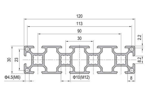
PG30 120 x 30 mm Ten Slot Aluminium Strut Profile Wide Multi Slot Rail
A 120 x 30 mm ten slot PG30 aluminium strut profile wide beam with 8.2 mm grooves on a 30 mm pitch. Four mounting positions per face for guard frames, accessory rails and service runs.
| Material | Aluminium |
|---|---|
| Alloy Grade | 6063-T5 |
| Temper | T5 |
| Section Size | 120 x 30 mm |
| Slot | 10 x 8.2 mm groove, 6 mm mouth, 30 mm pitch, outer pair 90 mm apart, M6 |
| Length | 6 m stock, cut to drawing to +/-0.5 mm |
| Tolerance | EN 755-9 / GB/T 6892, wall +/-0.15 mm |
| Surface | Mill finish / clear anodised / black anodised |
| MOQ | 200 m |
| Lead Time | Typically 20 to 30 days after deposit for mill finish |
| Loading Port | Shanghai, Ningbo, Qingdao |
| Supply Ability | Extrusion, cutting, machining and anodising in house |
| Payment Terms | T/T 30 per cent deposit, balance against copy of bill of lading; L/C at sight for larger orders |
| Trade Terms | FOB, CIF, CFR, EXW |
| Certifications | ISO 9001:2015, EN 755-9, RoHS and REACH declarations |
01What is the 120 x 30 mm ten slot profile?
How are the ten slots arranged?
Four on each 120 mm face and one on each 30 mm face. On the wide faces the grooves sit at 30 mm centres, so the outermost pair is 90 mm apart. That gives you four parallel fixing lines across the width of the member, which is what makes it useful as a rail rather than a beam.
What is it actually used for?
Machine guard and enclosure frames, accessory and sensor rails, cable and pneumatic line rails, display and exhibition frames, light partition and screen frames, and control panel frames. It is a wide, shallow rail rather than a deep beam: 120 mm of width to hang things on, 30 mm of depth to stiffen it.
Why ten slots and not four?
Because the width is there to be used. A 120 mm face with one central groove wastes 90 mm of it. Four grooves let you run separate services side by side: structure in one, cable in another, pneumatics in a third, and still leave one free.
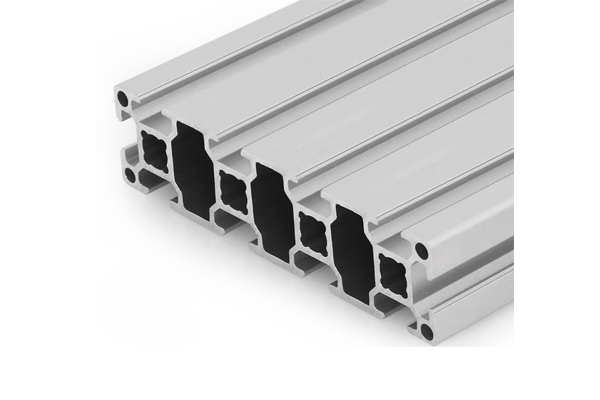
02Section data
| Item | Value | Note |
|---|---|---|
| Envelope | 120 x 30 mm | wide, shallow section |
| Slots | 10 | 8.2 mm groove, 6 mm mouth |
| Slot layout | 4 per 120 mm face, 1 per 30 mm face | as drawn |
| Slot pitch | 30 mm | between centres |
| Outer pair | 90 mm apart | across the widest two grooves |
| Fastener | M6 | 30 series slot nuts |
| Corner holes | 4.5 mm | tapped M6 |
| Centre bore | 10 mm | tapped M12 |
| Weight | approx. 2.70 kg/m | a 6 m bar is about 16.2 kg |
| Alloy | 6063-T5 | EN AW-6063 |
| Standard | EN 755-9 / GB/T 6892 | wall tolerance +/-0.15 mm |
| Length | 6 m stock | cut to drawing to +/-0.5 mm |
The centre bore is 10 mm tapped M12, which is unusually useful on a shallow section. It is how this member gets a proper end connection, because a 30 mm deep section has very little to work with at the ends otherwise.
03The four jobs a slot can have
Ten slots on one member invite a mistake: assuming all ten are equally useful. They are not. A slot’s usefulness depends on what is behind it, and on the member the material behind each slot is different.
The four grooves on a wide face sit at different distances from the edges and from the webs inside the section. The outer pair sits over the webs that run down the sides of the section, which is the stiffest place to put a load. The inner pair sits over the middle of the face, which is a good place to run services and a poor place to hang a heavy bracket.
Sorting the slots into four jobs before you design the assembly turns ten identical grooves into a wiring diagram, and it stops the classic failure where the cable tray and the sensor bracket both want the same groove.
| Job | Which slots | Why there | What goes in it |
|---|---|---|---|
| Load | outer pair on each wide face, 90 mm apart | they sit over the webs, which is the stiff path into the section | guard posts, brackets, feet, anything carrying weight |
| Cable | inner pair on one wide face | mid-face, away from the load path, easy to clip into | cable clips, trunking, harness runs, sensor leads |
| Pneumatics | inner pair on the opposite wide face | keeps air lines away from signal cable | tube clips, valve manifolds, air line runs |
| Panel | the groove on each narrow face | it faces the panel edge, which is where the panel is | panel edge clips, gasket carriers, infill retainers |
| Spare | whichever is left | a groove you did not allocate is a groove you can still use | later additions, rework, service modifications |
Two rules follow from that table. Separate the services: cable on one wide face, pneumatics on the other, because an air line running alongside a signal cable is a problem waiting to happen. And reserve a spare: on a ten slot member there is no excuse for using all ten, and the groove you leave empty is the one that saves a rework later.
04Wide and shallow: where the strength is
Use it as a rail
- Things are hung along the length, not across a span
- Services run inside the grooves
- It is supported at intervals by posts or a frame
- The 120 mm width is what you are buying
- It forms the top and bottom rail of a guard
- Panels clip into the narrow face grooves
Use a deeper section instead
- The member spans and carries a bending load
- Deflection governs: 30 mm of depth is very little
- The load is perpendicular to the wide face
- It is a beam in the structural sense
- You need stiffness more than fixing positions
- The 120 mm width is incidental
This is the honest limitation of the section and it is worth stating plainly: 120 mm of width with 30 mm of depth is a rail, not a beam. Used as a guard rail between posts at sensible centres it is exactly right. Used as a spanning member it will deflect visibly long before it is anywhere near its strength limit. If you need a wide member that spans, look at the 30 x 120 section used on edge, or step up to a deeper series.
05Failure modes to design out
| What goes wrong | Why it happens | Design it out by |
|---|---|---|
| Rail bows between posts | a shallow section was asked to span | add posts, or turn the section on edge so the 120 mm is the depth |
| Bracket pulls out of a mid-face groove | the load was hung on a groove with no web behind it | hang loads in the outer pair, over the webs |
| Air line and signal cable in the same groove | no service plan was drawn before assembly | allocate cable to one face and pneumatics to the other, on the drawing |
| No groove left for later | all ten were used on the first build | reserve at least one groove as spare and mark it on the drawing |
| M12 centre bore thread strips | the tapped engagement is short and the bolt was torqued to the steel figure | state the engagement length and torque to the aluminium figure |
06What to check before you order
Procurement checklist for the 120 x 30 mm ten slot section
- Confirm the series: 30 series is an 8.2 mm groove with a 6 mm mouth on a 30 mm pitch, M6.
- Confirm the slot allocation on the drawing: load, cable, pneumatics, panel and spare.
- Confirm the post centres if the member is used as a rail, so the shallow depth is not asked to span.
- Confirm whether the centre bore needs tapping M12 and to what depth.
- Confirm the corner holes need tapping M6.
- Confirm the accessory list as a 30 series kit: M6 slot nuts, cable clips, cover strips, end caps.
- Confirm the finish and the quantity in metres.
07Terms used on this page
- Web
- An internal wall running through a hollow section. Loads hung over a web follow a stiff path into the section; loads on mid-face do not.
- Outer pair
- The two grooves furthest apart on a wide face, here 90 mm apart. They sit over the webs and are the load-carrying pair.
- Services
- Cable, air lines and anything else routed along a frame rather than carried by it.
- Rail
- A member that things are hung along. It is supported at intervals and is not asked to span on its own.
- Cover strip
- A snap-in profile that closes an unused groove and keeps debris out.
- Centre bore
- The round hole down the middle of the section, here 10 mm and tapped M12.
08Questions buyers ask
How are the ten slots laid out?
Four on each 120 mm face at 30 mm centres, with the outer pair 90 mm apart, and one on each 30 mm face.
Which slots should carry a load?
The outer pair on each wide face. They sit over the internal webs, which is the stiff path into the section. Mid-face grooves are for services.
Is it strong enough to span between posts?
It is a rail, not a beam. With 30 mm of depth it deflects well before it reaches its strength limit. Keep post centres close, or use a deeper section.
What is the weight per metre?
Approximately 2.70 kg/m, so a 6 m stock length is about 16.2 kg.
What is the centre bore for?
It is 10 mm and tapped M12, which gives a shallow section a proper end connection that does not depend on the slot lips.
Can services be run inside the grooves?
Yes, that is the point of the wide face. Allocate cable to one face and pneumatics to the other so the two do not share a groove.
What we need to quote this section
- The section reference and the series, stated explicitly.
- The cut list with lengths and end preparation.
- The post centres or support spacing, so we can confirm the section is right.
- Whether the centre bore and corner holes need tapping, and to what depth.
- The accessory list as a 30 series kit, including cable clips and cover strips.
- The finish and the quantity in metres.
Quotations are broken out into extrusion, cutting, tapping, finish and hardware, so you can see which step is driving the cost. Browse the full aluminium profile catalogue and the 30 series aluminium profiles range for related sections.
Running services along a guard or machine frame?
Send the cut list, the post centres and the service plan. We quote extrusion, tapping, finish and the 30 series hardware as separate lines.
Request a quotationRelated Products
 PG40 120×120 mm Twelve Slot Aluminium Strut Profile with 62 mm Centre Bore
A 120 x 120 mm twelve slot PG40 aluminium strut profile with a 62…
 PG40 160×80 mm Twelve Slot Aluminium Strut Profile Heavy Beam for Gantry Frames
A 160 x 80 mm twelve slot PG40 aluminium strut profile heavy beam with…
 PG40 80×80 mm L-Shape Eight Slot Aluminium Strut Profile Corner Section
An 80 x 80 mm L-shape eight slot PG40 aluminium strut profile corner section…
 PG40 80×80 mm Eight Slot Heavy Aluminium Strut Profile High Load Column
An 80 x 80 mm eight slot heavy PG40 aluminium strut profile with diamond…
 PG40 160×40 mm Ten Slot Aluminium Strut Profile Wide Beam for Overhead Rails
A 160 x 40 mm ten slot PG40 aluminium strut profile wide beam with…
 PG40 160×40 mm Ten Slot Heavy Aluminium Strut Profile for Cantilever Arms
A 160 x 40 mm ten slot heavy PG40 aluminium strut profile with round…
 PG40 120×40 mm Eight Slot Aluminium Strut Profile Standard Beam for Table Frames
A 120 x 40 mm eight slot PG40 aluminium strut profile standard beam with…
 PG40 120×40 mm Eight Slot Heavy Aluminium Strut Profile for Machine Bases
A 120 x 40 mm eight slot heavy PG40 aluminium strut profile with round…
