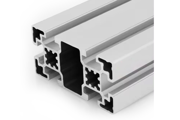
PG45 90×45 mm Six Slot Aluminium Strut Profile Rectangular Machine Beam
A 90 x 45 mm six slot PG45 aluminium strut profile for machine frames and long spans. Rectangular section, 45 mm slot pitch, tapped end bores and an 8 x 8 mm square bore in each corner.
| Material | Aluminium |
|---|---|
| Alloy Grade | 6063-T5 |
| Temper | T5 |
| Section Size | 90 x 45 mm |
| Slot | 6 x 10.2 mm groove, 10 mm mouth, 45 mm pitch, 2 slots per 90 mm face and 1 per 45 mm face, M10 |
| Length | 6 m stock, cut to drawing to +/-0.5 mm |
| Tolerance | EN 755-9 / GB/T 6892, wall +/-0.15 mm |
| Surface | Mill finish / clear anodised / black anodised |
| MOQ | 200 |
| Lead Time | 18-28 days after deposit for mill finish |
| Loading Port | Shanghai / Ningbo |
| Supply Ability | 300 t per month |
| Payment Terms | T/T 30% deposit + 70% before shipment | L/C at sight |
| Trade Terms | FOB | CIF | EXW |
| Certifications | ISO 9001:2015 | EN 755-9 | RoHS | REACH |
Structural framing · PG45 rectangular beam
A PG45 90 x 45 mm six slot aluminium strut profile is a rectangular beam on the 45 series groove system. Six 10.2 mm grooves are cut on a 45 mm pitch: two on each 90 mm face and one on each 45 mm face, with an 8 x 8 mm square bore in each of the four corners and a 12 mm centre bore in the web. It weighs about 4.1 kg/m and is supplied in 6063-T5.
The important number is not the size, it is the ratio. Stood on edge with the 90 mm dimension vertical the section has about 110 cm4; laid flat it has about 43 cm4. That is a factor of two and a half from turning the same piece of metal through ninety degrees. On a rectangular beam the orientation is a design decision with more effect than most of the sizing decisions around it, and it has to be made before the section is chosen rather than after.
Why a rectangular beam at all
A square column is the right answer for a post, because a post does not know which way the load will come from. A beam does know. A beam spans between two supports and carries load in one direction, so the section only has to be stiff about one axis. Putting material where it is not needed is weight you pay for on every metre, in every shipment, and on every lifting operation.
The 90 x 45 section takes that argument about as far as the 45 series groove system allows. It keeps the full 45 mm slot pitch in both directions so the whole accessory range still fits, but it puts 90 mm of depth in the direction that bends and only 45 mm in the direction that does not.
| Stood on edge | Laid flat | |
|---|---|---|
| Depth in the bending direction | 90 mm | 45 mm |
| Second moment of area | approx. 110 cm4 | approx. 43 cm4 |
| Relative stiffness | 2.6 x | Reference |
| Section depth to width | 90 x 45 mm | 45 x 90 mm |
| Slots available in the load face | 2 per 90 mm face | 2 per 90 mm face |
| Weight | approx. 4.1 kg/m | approx. 4.1 kg/m |
Orientation first, size second. A designer who picks the section and then decides how to sit it has the decision the wrong way round. On this beam the orientation is worth a factor of 2.6; going up a whole section size is worth about the same. One of those is free.
What the six slots are for
The slot layout is not decorative. Two grooves on each 90 mm face means the two working faces of the beam each carry a pair of mounting positions, and because the pitch is 45 mm the pair is exactly one 45 series accessory apart. A joining plate, a bracket or a linear rail can be bolted to two slots instead of one, which spreads the load and stops the fitting rotating under torque.
One groove on each 45 mm face means the narrow sides are still usable. In practice they are used for three things: a cover or guard panel fixed with panel strips, a cable duct clipped into the groove, and a second beam coming in at ninety degrees where the joint has to be made on the narrow face because the wide face is already occupied.
Corner bores and the centre bore
Each corner of the section carries an 8 x 8 mm square bore. These take M10 square nuts and are the reason a 45 series frame can be assembled with through bolts rather than only with slot nuts. The square shape is deliberate: it stops the nut turning while the bolt is tightened, so the joint can be made from one side with a single spanner.
The 12 mm bore in the web is the end face connection. It is tapped M14 at the end of the profile so a threaded bar or an end connector can be screwed in. Because the bore runs the full length, the same hole also carries services: on a machine frame it is common to run a cable or an air line down the inside of the beam rather than clipping it to the outside.
Span against load, in both orientations
The table below is for a simply supported beam at an L/500 deflection limit, which is the usual limit for a machine frame where alignment matters. Uniformly distributed load and a single central point load are both given, because most real beams are somewhere between the two and it is quicker to bracket the answer than to calculate it.
| Span | On edge, distributed | On edge, central point | Flat, distributed | Flat, central point |
|---|---|---|---|---|
| 1.0 m | approx. 7.9 kN | approx. 4.9 kN | approx. 3.1 kN | approx. 1.9 kN |
| 1.5 m | approx. 3.5 kN | approx. 2.2 kN | approx. 1.4 kN | approx. 0.86 kN |
| 2.0 m | approx. 2.0 kN | approx. 1.2 kN | approx. 0.77 kN | approx. 0.48 kN |
| 2.5 m | approx. 1.3 kN | approx. 0.79 kN | approx. 0.49 kN | approx. 0.31 kN |
| 3.0 m | approx. 0.88 kN | approx. 0.55 kN | approx. 0.34 kN | approx. 0.21 kN |
Read the flat columns as a warning rather than as an option. A 90 x 45 beam laid flat at 2 m will carry less than 800 N distributed, which is within the reach of a person leaning on it. If the drawing shows the beam flat, either the load is genuinely small or the section is the wrong one.
The joint at each end
The end of a rectangular beam is the part that is easiest to get wrong, because the beam is stiff in one direction and only moderately stiff in the other, and the joint has to cope with both. The rule that follows is simple: never make a rectangular beam’s end connection carry the bending moment on its own.
Where a 90 x 45 beam meets a 90 x 90 column, the correct detail is an angle bracket or a joining plate bolted into the beam’s side slots and into the column’s face slots. The bracket transfers the moment into the column over a spread of fixings instead of through a single end face. An end face connector screwed into the 12 mm bore is fine for locating the beam and for carrying shear, but it should not be the only thing holding a loaded span.
Choosing the orientation on the drawing
- Draw the load direction first Not the frame outline — the load. A beam that carries a panel, a guard or a machine unit knows which way that weight points.
- Put the 90 mm dimension along the load This is the whole point of a rectangular section. If the 90 mm dimension ends up across the load, the design is paying for depth it is not using.
- Check the second direction If the beam also has to resist a side load, a wind load or a person leaning on it, check the flat figure as well. It is usually the one that fails.
- Keep the slot faces clear The two 90 mm faces are the working faces. Do not bury them against a panel unless the panel is meant to be fixed there.
- Then choose the wall Once the orientation is fixed, the wall thickness is the remaining variable. On this beam the standard wall is the general purpose choice and the heavy wall is for concentrated loads rather than for stiffness.
Frequently asked questions
Is a 90 x 45 mm beam stiffer than an 80 x 80 mm one?
Only in one direction. Stood on edge the 90 x 45 section has about 110 cm4 against roughly 130 cm4 for an 80 x 80 section, so they are close; laid flat it drops to about 43 cm4 and the square section wins easily. If the load direction is known, the rectangular beam wins on weight. If it is not, the square section is the safe answer.
What is the 45 mm pitch for?
It is the 45 series slot pitch, so the two grooves on each 90 mm face sit exactly one accessory apart. That lets a bracket or a joining plate be bolted into two slots instead of one, which is what stops the fitting rotating when the bolts are tightened.
Can I tap the end of the profile?
Yes. The 12 mm centre bore is normally tapped M14 at the end, and the four 8 x 8 mm corner bores take M10 square nuts. Both are intended for end face connections and both are available on the standard wall, unlike on the light sections in the range.
How many slots are there and where?
Six in total: two on each 90 mm face on a 45 mm pitch, and one on each 45 mm face. The two 90 mm faces are the structural faces; the 45 mm faces are for panels, ducts and cross connections.
What length does it come in?
6 m stock as standard, cut to drawing to plus or minus 0.5 mm. Longer lengths can be produced on request, and short cut lengths are bundled to the cut list so the assembly sequence is preserved.
Send the span, the load and which way it acts
Tell us the span, the load and the direction it acts in. We will confirm the orientation, the wall thickness and the end connection in one reply.
Request a QuoteRelated Products
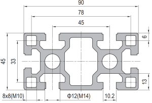 PG45 90 x 45 mm Six Slot Aluminium Strut Profile Heavy Rectangular Beam
90 x 45 mm six-slot heavy aluminium strut profile with 10.2 mm grooves and…
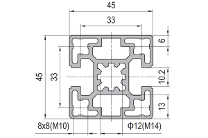 PG45 45 x 45 mm Two Slot Type B Aluminium Strut Profile Opposite Rail
45 x 45 mm two-slot Type B aluminium strut profile with slots on opposite…
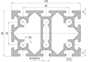 PG40 120 x 80 mm Ten Slot Aluminium Strut Profile Wide Heavy Beam
120 x 80 mm ten-slot aluminium strut profile with six slots on the two…
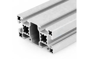 PG40 80×40 mm Six Slot Aluminium Strut Profile Standard Wall Beam
An 80 x 40 mm six slot standard wall PG40 aluminium strut profile. Two…
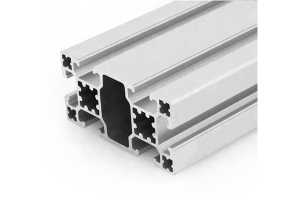 PG40 80×40 mm Six Slot Light Aluminium Strut Profile for Panel Frames
An 80 x 40 mm six slot light wall PG40 aluminium strut profile for…
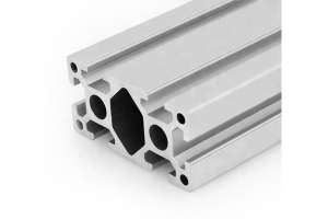 PG40 80 x 40 mm Six Slot Aluminium Strut Profile Heavy Rectangular Beam
80 x 40 mm heavy-wall six-slot aluminium strut profile with four slots on the…
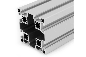 PG40 80×80 mm Eight Slot Aluminium Strut Profile Square Column
An 80 x 80 mm eight slot standard wall PG40 aluminium strut profile square…
 PG30 30×30 mm Four Slot Aluminium Strut Profile Standard Wall Column
A 30 x 30 mm four slot standard wall PG30 aluminium strut profile square…
