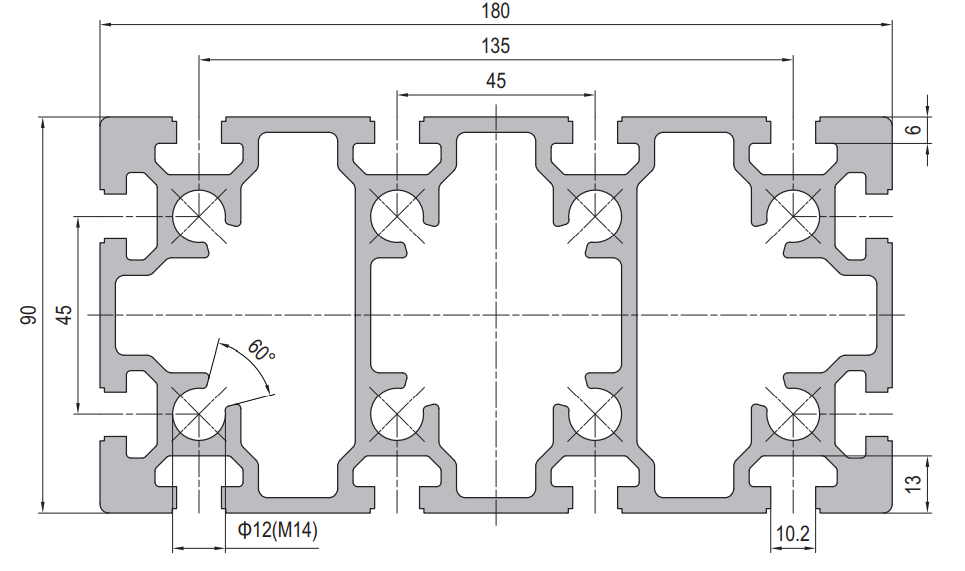
Aluminium Profile CNC Router Gantry 90 x 180 mm Twelve Slot Beam
90 x 180 mm twelve slot aluminium profile at about 9.50 kg/m for a CNC router gantry beam, with rail seats machined in one setup and M10 slots for the carriage and uprights.
| Material | Aluminium |
|---|---|
| Alloy Grade | 6063-T5 |
| Temper | T5 |
| Section Size | 90 x 180 mm, twelve slots |
| Slot | 12 x 10 mm groove, M10 hardware |
| Length | Cut to the gantry length, rail seats machined to the drawing |
| Tolerance | Cut length +/-0.5 mm, rail seat flatness and co-planarity to the drawing, section to EN 755-9 |
| Surface | Mill finish / clear anodised / black anodised, with rail seats masked where the height matters |
| MOQ | One beam; matched pairs quoted together |
| Lead Time | 2 to 3 weeks for mill finish, plus 1 to 2 weeks for rail seat machining, plus about a week for anodising |
| Loading Port | Shanghai / Ningbo |
| Supply Ability | Long-bed machining for rail seats, with matched pair production for two-beam gantries |
| Payment Terms | T/T 30% deposit + 70% before shipment | L/C at sight |
| Trade Terms | FOB | CIF | EXW |
| Certifications | Dimensional report including rail seat flatness and co-planarity, material certificate to EN 10204 3.1 on request |
01Is bending or torsion the real limit on a gantry beam?
Torsion, in almost every router that fails. A 90 x 180 mm twelve slot aluminium profile is very stiff in bending about its strong axis and much less stiff in torsion, because the slots open up the section and an open section twists easily. On a gantry, an off-centre cutting load applies a torque along the whole span, and the resulting twist at the tool shows up as a cut that is deeper on one side.
That is why a single-beam gantry is limited by how far off centre the spindle can go, not by how much the beam sags at mid span. If the machine has to cut across the full width, the answer is usually two beams separated in the Y direction, connected by a plate at each end — the pair resists torsion as a closed box, and each beam only carries its share of the bending.
Numbers on this page are estimates from the mass and the envelope, with the assumptions written out. They are here so the arithmetic can be repeated with real section data, not to replace the section data sheet.
02How much does it deflect at 2 m?
The section weighs about 9.50 kg/m, which back-calculates to a cross-section of roughly 3519 mm2. With an envelope of 90 x 180 mm and a perimeter of 540 mm, that gives an average wall of about 6.5 mm. Treating the section as a rectangular tube with that average wall, the second moment of area is about 1390 cm4 about the strong axis and about 460 cm4 about the weak axis — estimates that ignore the slot grooves, so the real values will be lower.
- Load P (assumed)
- 500 N, a 50 kg Z carriage and spindle
- Span L
- 2000 mm, simply supported
- E, aluminium
- 70 000 N/mm2
- I, strong axis (estimated)
- about 1.39 x 10^7 mm4
- Deflection
- 500 x 2000^3 / (48 x 70 000 x 1.39 x 10^7) = about 0.086 mm
- I, weak axis (estimated)
- about 4.6 x 10^6 mm4, three times softer
| Span | Deflection, strong axis | Deflection, weak axis |
|---|---|---|
| 1500 mm | about 0.036 mm | about 0.108 mm |
| 2000 mm | about 0.086 mm | about 0.258 mm |
| 2500 mm | about 0.168 mm | about 0.503 mm |
| 3000 mm | about 0.290 mm | about 0.870 mm |
Two conclusions follow. First, the beam has to be oriented with its 180 mm depth in the bending direction — mounted the other way round it is three times softer and the numbers in the right-hand column apply. Second, deflection grows with the cube of the span, so a 3 m gantry is not 50 percent worse than a 2 m gantry, it is more than three times worse.
03Why must the rail face be machined?
Because a linear rail is far straighter than an extrusion. The extrusion standard allows a straightness and a twist that are entirely acceptable for a frame and completely unacceptable for a rail seat. Bolt a rail onto an as-extruded face and one of two things happens: the rail follows the profile and the carriage binds, or the rail stays straight and the bolts preload it into a curve, which shortens its life.
- Machine the rail seat, one pass, along the full length, in a single setup. A seat machined in two setups has a step at the joint that the rail will find.
- Machine both rail seats in the same setup if the two rails are on the same beam. That is the only way to get co-planarity without a surface plate and a lot of shimming.
- Machine the mounting face, not the slot. A rail bolted through the slot sits on whatever the slot flange happens to be, which is neither flat nor parallel.
- Anodise after machining, and mask the rail seat if the coating thickness would affect the height. A 15 micron coating on one seat and not the other is a 15 micron misalignment.
- Expect the machining to cost more than the profile. It is a long single-pass operation on a big machine, and it is the operation that decides whether the router cuts accurately.
04How do you get two rails co-planar?
There are three ways and they are ranked by how much of the accuracy survives shipping.
| Approach | How it works | Achievable co-planarity | Trade-off |
|---|---|---|---|
| Machine both seats in one setup | Both faces cut in the same pass on one beam | The best available, set by the machine | Needs a long machine and a big setup |
| Two beams, machined as a pair | Both beams clamped together and cut together | Good, and it survives assembly if the pair is not separated | The pair must be shipped and handled as a matched set |
| Shim and indicate on assembly | Rails aligned with a dial gauge and shim stock | Workable, and it depends entirely on the fitter | Skilled labour, and it does not survive a re-assembly |
| No machining, bolt to the extrusion | Not an alignment method | Whatever the extrusion happened to be | Binds, and it is the most common mistake |
The practical instruction: decide at drawing stage whether the rails are on one beam or two. One beam means one setup and the best result. Two beams means they must be machined as a pair, marked as a pair, and shipped as a pair — and if they are ever separated in the workshop, the alignment has to be re-done.
05Does beam mass matter?
It matters on a moving gantry and it does not matter much on a fixed one. That single distinction decides whether this section is a good idea.
Moving gantry, beam travels
- Beam mass is part of the moving mass, so it limits acceleration
- 9.50 kg/m means a 2 m beam is about 19 kg before the Z axis
- Acceleration force is mass times acceleration, so the motor and the frame both pay
- A lighter section or a fixed gantry is often the better machine
- Rigidity and mass pull in opposite directions here
Fixed gantry, table travels
- Beam mass is irrelevant to the motion, only to the floor loading
- Stiffness is the only criterion, so use the deepest section that fits
- The moving mass is the table and the workpiece, which is usually heavier anyway
- Deflection at the tool is the whole design problem
- This is where a 90 x 180 section is straightforwardly the right answer
On a moving gantry there is a further trap: the acceleration force is applied to the beam as a bending load, because the beam has to accelerate its own middle. A 19 kg beam accelerating at 2 m/s2 is a distributed load of about 38 N/m along its length, on top of gravity and the cutting force. That is usually small compared with the cutting load, but it is at a different frequency, which is why a light gantry can sound fine and still chatter.
06What is the assembly order?
Sequence matters more than torque here, because every step after the rail is fixed can only make the alignment worse.
- Machine the rail seats. Before anything is assembled.
- Bolt the gantry beam to its uprights, and check the beam is level and square to the X axis before the rails go on.
- Fix the master rail first, then indicate the second rail to the first, not to the machine frame.
- Torque in a cross pattern from the centre outward, so the rail is not pulled into a bow by sequential tightening.
- Fit the carriage and run it the full length by hand before any motor is connected. If it binds, the alignment is wrong and no amount of motor torque will fix it.
- Re-check after the first day of cutting. A new machine settles, and the rail bolts that were correct on assembly are often not correct after a shift of cutting.
07Where is the ceiling for an aluminium gantry?
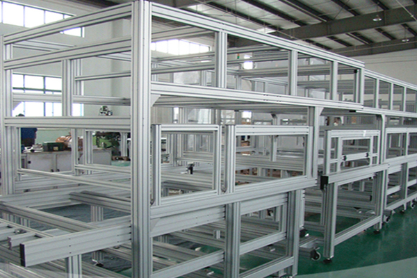
Around 2.5 to 3 m of span for a single beam, and around 4 m for a properly braced pair. Beyond that the section gets so deep that the mass and the cost stop making sense, and the machine wants a welded steel fabrication or a cast iron bridge instead.
- Above about 3 m, the beam depth needed to hold deflection drives the mass up, and on a moving gantry that is self-defeating.
- Above about 4 m, torsion on a single beam is unmanageable and the pair becomes mandatory.
- Where the accuracy requirement is tighter than about 0.05 mm at the tool, aluminium profile is usually the wrong material — not because of stiffness but because of thermal growth and damping.
- Where the machine cuts aluminium or steel, the cutting forces are high enough that a profile gantry is a compromise. Wood, plastic, foam and composites are where it belongs.
Gantry beam checklist
- Span, and whether the gantry moves or the table moves
- Orientation: 180 mm depth in the bending direction
- Load at the tool, including the Z carriage and the spindle
- Deflection budget at the tool, and the span that meets it
- Torsion: single beam or a braced pair
- Rail seats: machined in one setup, or two beams machined as a pair
- Co-planarity method, and who is responsible for it on assembly
- Anodising and masking of the rail seats
- Assembly sequence and the torque pattern
- Whether the uprights are stiff enough to let the beam do its job
08Questions from machine builders
Related sections and categories
Browse 45 Series Aluminium Profiles, Strut Profiles, or see the 90 x 180 mm twelve slot section for the full section data, and the 45 x 180 mm ten slot section when the beam has to be shallower in one direction.
What span can a 90 x 180 aluminium profile gantry cover?
About 1.5 to 2.5 m for a single beam at a deflection budget around 0.1 mm, and up to about 4 m for a properly braced pair. Beyond that a welded steel fabrication is usually the better answer.
Why does my gantry cut deeper on one side?
Torsion. An off-centre cutting load twists the beam along its length, and an open slotted section twists easily. Two beams separated in Y resist it as a closed box.
Do the rail faces have to be machined?
Yes. An extruded face has straightness and twist that are acceptable for a frame and unacceptable for a linear rail seat. Machining both seats in one setup is the only way to get co-planarity without shimming.
Which way round should the section be mounted?
With the 180 mm depth in the bending direction. Mounted the other way round the section is roughly three times softer, and the deflection numbers triple.
How much does the beam weigh?
About 9.50 kg/m, so a 2 m beam is about 19 kg before the Z axis. On a moving gantry that mass limits acceleration; on a fixed gantry it only affects floor loading.
Can you machine the rail seats?
Yes, one pass along the full length, and both seats in the same setup where they are on one beam. Send the rail positions and the co-planarity requirement with the drawing.
What to send for a gantry beam quote
- Span, and whether the gantry or the table moves
- Rail positions, rail type, and the co-planarity requirement
- Load at the tool, including the Z carriage and spindle
- Deflection budget, and where it is measured
- Single beam or a braced pair
- Machining: which faces, and whether the seats are to be cut in one setup
- Finish and masking of the rail seats
- Upright and connection details, if the beam is part of a frame package
- Quantity, and whether beams are to be shipped as matched pairs
The co-planarity requirement is the number that decides the price. Say what it is, and say where it is measured, because a rail seat measured at the ends reads differently from one measured at the middle.
Send the gantry drawing
Span, rail type, rail positions and the co-planarity you need are enough. Tell us whether the gantry moves or the table moves — it decides whether mass or stiffness is the governing problem.
Request a quotationRelated Products
 Aluminium Profile Truck Body Frame 50 x 100 mm for Dry Freight Boxes
50 x 100 mm six slot aluminium profile at about 5.40 kg/m for dry…
 Solar Mounting Aluminium Rail 45 x 45 mm for PV Array Frames
45 x 45 mm four slot aluminium profile at about 2.55 kg/m, used as…
 45 x 180 mm Aluminium Extrusion for Typhoon-Zone Frames
45 × 180 mm aluminium extrusion in 6063-T5 for outdoor frames in the Philippine…
 Aluminium Profile for Sale: 45 x 60 mm Cut to Length, No Minimum Run
45 x 60 mm aluminium profile in 6063-T5, sold by the length or by…
 20 x 80 mm Narrow Aluminium Profile for Textile and Diamond Machinery
20 x 80 mm ten slot narrow aluminium profile in 6063-T5 for machinery where…
 45 x 180 mm Aluminium Extrusion: Arrival Inspection for Importers
45 × 180 mm aluminium extrusion in 6063-T5 for importers clearing at Nhava Sheva.…
 45 x 90 mm Aluminium Profile for Pharma Cleanroom Framing
45 x 90 mm aluminium extrusion in 6063-T5 for GMP cleanroom framing. Six 10.2…
 45 x 60 mm Aluminium Profile for Textile Machine Frames
45 x 60 mm four-slot aluminium extrusion in 6063-T5 for loom, winder and conveyor…
