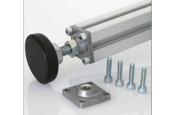
Foot Mounting Plate
Adapter plate bolted to the end of a profile leg that presents a standard bolt pattern underneath, so a range of feet and castors all fit the same leg.
| Material | Aluminium 6063-T5 or steel |
|---|---|
| Alloy Grade | 6063-T5 or S235 steel |
| Temper | custom |
| Section Size | Fits 40, 45 and 60 series and 40x80 mm sections |
| Slot | Top pattern M8-M12; bottom 60x60 / 100x100 mm |
| Length | Plate 80x80 to 100x100 mm; 6-12 mm thick |
| Tolerance | ±0.2 mm on hole positions |
| Surface | Anodised, powder coated or zinc plated |
| MOQ | 200 |
| Lead Time | 15-25 days after deposit |
| Loading Port | Shanghai / Ningbo |
| Supply Ability | 80,000 pcs per month |
| Payment Terms | T/T 30% deposit + 70% before shipment | L/C at sight |
| Trade Terms | FOB | CIF | EXW |
| Certifications | ISO 9001:2015 | ISO 14001 | RoHS | REACH |
Floor elements · Interface standard
A foot mounting plate is the interface between the end of a profile leg and whatever is fixed under it — a castor, a levelling foot, or the floor. It bolts to the profile end taps on top and presents a standard bolt pattern underneath.
Its value is standardisation. Without it, every foot and castor has to be matched to the profile end taps, which means the leg geometry changes whenever the specification changes. With it, one leg takes any of the standard feet and castors, so a product can be offered with fixed feet, levelling feet or castors as options without three different frame drawings. That is the reason it appears in OEM programmes: it is an interface, not a structural part.
Why an interface part is worth having
- One leg, several options. A frame designed around a mounting plate can be built as a fixed-foot version, a levelling version or a mobile version from the same cut list. Only the plate’s underside attachment changes.
- Spares and upgrades. A customer who wants castors later does not need a new frame — the plate is already there and takes the castor directly.
- Repeated builds. On a production run, the plate removes the variation in the leg end. Every leg is identical and the foot choice is made at the end of the line.
- Tolerance control. The plate is machined to a tight pattern, so the bolt spacing under the leg is accurate even when the profile end taps are not. That matters for a castor, which has to swivel without binding.
What the plate presents on each side
| Profile end (top) | Plate | Underside (bottom) |
|---|---|---|
| 4 × M8 end taps, 40 series | 80 × 80 mm plate | 60 × 60 mm castor pattern, 4 × Ø9 |
| 4 × M8 end taps, 45 series | 90 × 90 mm plate | 60 × 60 or 100 × 100 castor pattern |
| 4 × M10 end taps, 60 series | 100 × 100 mm plate | 100 × 100 castor pattern |
| 4 × M8 end taps, 40 × 80 | 80 × 120 mm plate | 60 × 60 castor pattern, centred |
| Threaded insert, any series | 80-100 mm plate | M12 / M16 threaded boss |
Plate, boss or both
The underside of the plate can carry either a bolt pattern, a threaded boss, or both. A bolt pattern takes a plate-mounted castor or a base plate. A threaded boss takes a levelling foot or a thread-stem castor. A plate with both lets the same leg end accept either, which is the most flexible arrangement and the one used on products that are offered in several configurations.
The plate thickness is set by the castor load, not by the profile. A castor transfers its load into the plate at the four bolt positions, and a thin plate flexes between them, which lets the castor tilt and bind. On a heavy castor the plate is 10 or 12 mm rather than 6 mm.
- Confirm the profile end taps The plate bolts into the M8, M10 or M12 end taps of the profile. Confirm the tap size and spacing before the plate is drawn.
- Choose the underside Bolt pattern for a plate-mounted castor or base plate; threaded boss for a levelling foot or thread-stem castor; both for maximum flexibility.
- Size the thickness Set by the castor or foot load. 6 mm for light duty, 8 mm general, 10-12 mm for heavy castors.
- Fit the plate to the leg Bolt the plate to the profile end first, then fit the castor or foot to the plate. That sequence keeps the castor swivel clear while the leg bolts are torqued.
- Check the swivel clearance On a castor, confirm the swivel head clears the plate edge through its full rotation. A plate that is too small lets the castor hit it on a tight turn.
Practical point: if a product is going to be offered with a choice of feet, design the mounting plate in at the start. Retrofitting a plate to a frame whose legs are already cut for direct-mount feet means re-cutting the legs, which is far more expensive than the plate.
Frequently asked questions
Does the plate add height to the frame?
Yes, by its own thickness — typically 6 to 12 mm. That has to be allowed for in the leg length at the design stage.
Can one plate take both a castor and a levelling foot?
Yes, the combined version has a bolt pattern and a central threaded boss, so either can be fitted to the same plate.
Will the plate fit any 40 series profile?
It fits any 40 series profile with the standard 40 series end tap spacing. Profiles from different ranges can differ in tap position, so confirm against the section drawing.
Is a mounting plate needed if the castor already has a plate?
Not always. If the castor plate pattern matches the profile end taps directly, the mounting plate is redundant. It earns its place when the patterns differ or when the leg end has to accept more than one type of foot.
Can the plate be supplied undrilled on one side?
Yes, for a customer who wants to drill the underside pattern on site. It is supplied flat with the site-drilled face uncoated.
Send the leg end and the foot you want to fit
Tell us the profile end taps and the foot or castor that has to fit under it. We will design the interface plate, confirm the height it adds and return FOB pricing within one working day.
Request a QuoteRelated Products
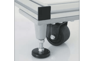 Foot and Castor Components
Spare and replacement components for foot and castor installations — pads, stems, locking nuts,…
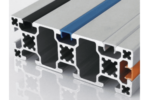 T-Slot Cover Profile
Snap-in T-slot cover strip that closes the open slot on aluminium framing profiles, giving…
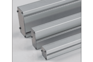 Aluminium Conduit End Cap
Snap-fit or screw-fixed end caps for aluminium conduit profiles from 40x40 to 80x200 mm,…
 Aluminium Profile End Cap
Push-fit end caps for T-slot framing profiles from 15 to 60 series, sized to…
 T-Slot Reducing Profile
Reducing insert that narrows a wide T-slot to accept standard nuts and accessories from…
 Swivel Ball Foot
Self-aligning levelling foot with a ball-and-socket joint between stem and pad, keeping the pad…
 Swivel Foot with Mounting Holes
Levelling foot with a drilled base pad so the frame can be anchored to…
 Nylon Pivot Foot
Levelling foot with a moulded PA6 nylon pivot joint and base, selected for vibration…
