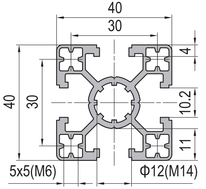
Strut Aluminium Profile 40×40 mm 4-Slot T-Slot Extrusion Machine Frame
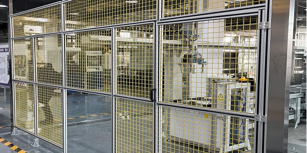
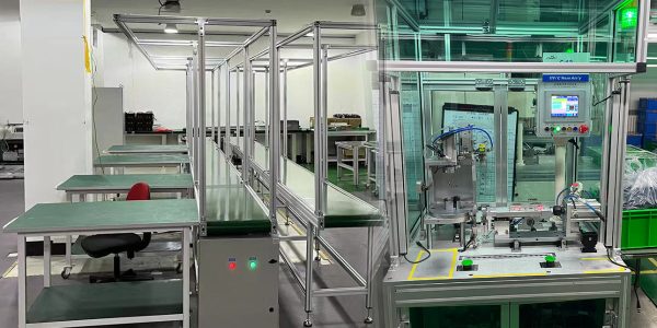
40 x 40 mm four-slot T-slot strut aluminium profile in 6063-T5 with M6 slots on all four faces and an M14 centre bore. The standard member for machine frames, guards, workbenches and automation cells.
| Material | Aluminium |
|---|---|
| Alloy Grade | 6063-T5 |
| Temper | T5 |
| Section Size | 40 x 40 mm |
| Slot | M6 slot, 8 mm mouth, 4 faces, 30 mm pitch |
| Length | 6 m stock, cut to drawing to +/-0.5 mm |
| Tolerance | EN 755-9 / GB/T 6892, wall +/-0.15 mm |
| Surface | Mill finish / clear anodised / black anodised |
| MOQ | 500 |
| Lead Time | 15-25 days after deposit for mill finish |
| Loading Port | Shanghai / Ningbo |
| Supply Ability | 600 t per month |
| Payment Terms | T/T 30% deposit + 70% before shipment | L/C at sight |
| Trade Terms | FOB | CIF | EXW |
| Certifications | ISO 9001:2015 | EN 755-9 | RoHS | REACH |
Structural framing · 40 series
A 40 × 40 four-slot strut profile is an extruded aluminium section with a T-slot on each of its four faces and a 40 mm square envelope. In practice it is the default member in industrial framing: if a drawing says “aluminium profile frame” and nothing else, the member is usually this section. The reason is not that it is the strongest or the cheapest — it is that the whole accessory ecosystem, from T-slot nuts and joining plates to levelling feet and panel fixings, is dimensioned around it, so a frame designed in 40 × 40 can be built without a single custom part.
The section carries an M6 slot on all four faces and an M14 bore through the centre. Those two features do different jobs and it is worth keeping them apart: the slots take the accessory fixings and let a joint be made anywhere along the member, while the centre bore takes a long through-bolt where a joint has to carry tension across the full width of the section. We extrude it in 6063-T5 to the standard 40-series geometry, in light, standard and heavy wall, and supply it cut to length, tapped, machined or as a welded assembly.
Why 40 x 40 four-slot became the default
Framing systems are only as useful as their accessory range, and the accessory range that grew up around 40 × 40 is the largest of any section. That is a self-reinforcing effect: because more frames are built in 40 × 40, more brackets, hinges, handles, feet and cable ducts are made for it, which makes it the safe choice for the next frame. A designer who picks an unusual section to save 8 % on material often loses that saving several times over on the first joint that needs a machined adaptor.
There is also a practical limit that the 40 mm envelope happens to sit just inside. Below roughly 30 mm, the slot mouth is too small for a bolt that can carry a real load, and the wall behind the slot is too thin to tap. Above roughly 60 mm, the member stops being a frame part and becomes a beam, with the weight and cost to match. 40 × 40 is the largest section that still behaves like a convenient framing component and the smallest that still behaves like a structural member.
| Property | Light wall | Standard | Heavy wall |
|---|---|---|---|
| Envelope | 40 x 40 mm | 40 x 40 mm | 40 x 40 mm |
| Slot | M6 (8 mm mouth) | M6 (8 mm mouth) | M6 (8 mm mouth) |
| Slot pitch | 30 mm | 30 mm | 30 mm |
| Centre bore | O 6.8 mm | O 8.2 mm | O 8.2 mm |
| Centre bore tapped | M8 | M14 | M14 |
| Moment of inertia | approx. 6.1 cm4 | approx. 9.2 cm4 | approx. 12.4 cm4 |
| Weight | approx. 1.30 kg/m | approx. 1.75 kg/m | approx. 2.35 kg/m |
| Standard length | 6 m | 6 m | 6 m |
What the M6 slot and the M14 bore each carry
Confusing these two is the most common cause of a joint that looks right and fails. A slot fixing carries load through the two lips of the slot, so its capacity is limited by how much the lips can resist being pulled together and by how much of the slot length the nut engages. A through-bolt in the centre bore carries load through the whole section, but it can only be used where you can reach both ends of the member.
Three things a 40 x 40 four-slot profile will not do
First, it will not act as a long unsupported span. At 40 mm depth the section deflects visibly under its own weight plus a modest load once the span passes roughly 1.2 m. Where a frame needs a clear opening wider than that, the member has to change — a 40 x 60 rectangular section turned on edge, or a 50 x 100 heavy beam — rather than a bigger bolt in the same section.
Second, it will not give a sealed face. All four faces are open slots, so the section cannot be used where the frame itself has to be dust-tight or washdown-rated without slot cover strip and a gasket detail. Where a closed face is genuinely needed, a three-slot section is the correct starting point.
Third, it will not take a thread directly in the slot wall. The wall behind an M6 slot mouth is around 4 mm, which is not enough for a reliable tapped hole under load. Any connection into the side of the member goes through a T-slot nut or a machined block, never a tapped hole in the extrusion wall.
Rule of thumb for the design stage: if a joint has to be made and unmade on site, use slot fixings; if it has to carry the weight of the machine, use the centre bore. If both, use both — the extra bolt costs less than the field failure.
Specifying it so it arrives usable
- Fix the wall thickness first Light, standard and heavy wall look identical in a 2D layout but differ by roughly 35 % in weight and nearly 100 % in stiffness. State it on the order, or the factory will supply whichever is running.
- Give a cut list, not a total length Tolerance on a cut length is ±0.5 mm, but that is per piece. Thirty members at ±0.5 mm will not assemble into a frame with a square corner, so we cut and deburr to the drawing and bag by assembly.
- Say which ends are tapped A tapped centre bore at the member end is a machining operation, not an extrusion feature. Tapping M14 to a stated depth costs little when it is done with the cut; it costs a lot when it is discovered on site.
- State the finish Mill finish is standard and cheapest. Clear or black anodising adds a lead-time step and a colour-batch risk on mixed orders, so if the frame is visible, anodise the whole order in one batch.
Matching components and where they go
A 40 × 40 frame needs very little beyond the section itself. Corner joints are normally made with an angle bracket or a joining plate; mid-span joints and tee joints use a butt connector. Feet are either a base plate or a levelling foot depending on whether the frame has to sit flat or be adjusted. Panels are held with panel mounting blocks or strips, and the slot is closed with cover strip where the face is visible.
Every one of those parts is dimensioned for the 8 mm slot and the 30 mm slot pitch of this section. That is the practical value of staying inside the 40-series standard: the parts fit, and they fit without a drawing.
Frequently asked questions
Is 40 x 40 four-slot the same as 40 series T-slot from other suppliers?
The 40 mm envelope and the 30 mm slot pitch are common, but the slot mouth and the internal groove depth are not guaranteed to match. Accessories are made to a specific groove, so if you are mixing sections from two sources, send both section drawings and we will confirm whether one supplier’s nuts retain in the other’s slot.
What is the maximum span before I need a bigger section?
As a working guide, keep an unsupported span under about 1.2 m for a lightly loaded member and under about 0.8 m if the member carries a load or has to stay visually straight. Beyond that, change the section or add a mid-span support rather than increasing the bolt size.
Can you supply it cut, tapped and machined to a drawing?
Yes. We cut to ±0.5 mm, deburr, tap centre bores and slot ends, drill and counterbore for brackets, and machine mitres or notches. Send DWG, DXF, STEP or PDF and we will quote from the drawing rather than from a length list.
How much does a 40 x 40 profile weigh per metre?
Around 1.30 kg/m in light wall, 1.75 kg/m in standard wall and 2.35 kg/m in heavy wall, all in 6063-T5. The exact figure depends on the die, so treat these as planning numbers and ask for the certified figure on the die you are ordering.
Do you anodise, and does it change the slot dimensions?
We supply mill finish, clear anodised and black anodised. Anodising builds a layer of roughly 10 to 20 microns depending on the class, which is inside the slot tolerance but does affect a tight sliding fit. Where a nut has to slide freely, specify the anodising class at the enquiry stage.
Send the frame drawing, get a cut list and a price
Tell us the wall thickness, the cut list and which ends are tapped. We will return the section weight, the machining operations and FOB pricing, and supply the members cut, deburred and bagged by assembly so the frame goes together on site without rework.
Request a QuoteRelated Products
 Strut Aluminium Profile 20×40 mm 2-Slot T-Slot Extrusion for Light Frames
20 x 40 mm two-slot T-slot strut aluminium profile in 6063-T5 with two M6…
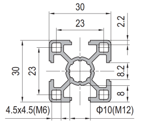 Strut Aluminium Profile 30×30 mm 4-Slot Light T-Slot Extrusion
30 x 30 mm light-wall four-slot T-slot strut aluminium profile in 6063-T5 with M5…
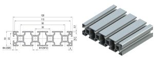 Strut Aluminium Profile 30×120 mm 3-Slot Wide Beam T-Slot Extrusion
30 x 120 mm three-slot wide-beam T-slot strut aluminium profile in 6063-T5 with three…
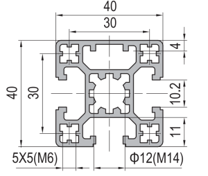 Strut Aluminium Profile 40×40 mm 3-Slot T-Slot Extrusion Closed Face
40 x 40 mm three-slot T-slot strut aluminium profile in 6063-T5 with one solid…
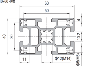 Strut Aluminium Profile 40×60 mm 4-Slot Rectangular T-Slot Extrusion
40 x 60 mm four-slot rectangular T-slot strut aluminium profile in 6063-T5 with M6…
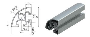 Radius Corner Aluminium Profile 45×45 mm Quarter Round Trim Section
45 x 45 mm quarter-round radius corner aluminium trim section in 6063-T5 with an…
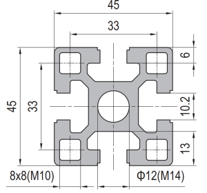 Strut Aluminium Profile 45×45 mm 4-Slot Heavy Duty T-Slot Extrusion
45 x 45 mm heavy duty four-slot T-slot strut aluminium profile in 6063-T5 with…
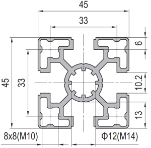 Strut Aluminium Profile 45×45 mm 4-Slot Light T-Slot Extrusion
45 x 45 mm light wall four-slot T-slot strut aluminium profile in 6063-T5 with…
