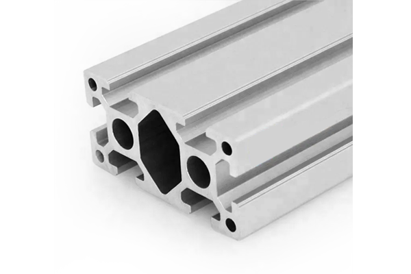
4080 Profile: 40 x 80 mm Aluminium Span and Load Limits
40 x 80 mm six-slot aluminium extrusion in 6063-T5, 3.60 kg/m, with the section properties and span tables published: about 40 cm4 strong axis and 75 kg/m allowable at 2 m for L/360.
| Material | Aluminium |
|---|---|
| Alloy Grade | 6063-T5 |
| Temper | T5 |
| Section Size | 80 x 40 mm, six slots |
| Slot | 6 x 10.2 mm groove, 8 mm mouth, 40 mm pitch, two per long face and one per short face, M8 |
| Length | 6 m stock; cut to list to +/-0.5 mm |
| Tolerance | EN 755-9, wall +/-0.15 mm; straightness 1.5 mm per metre; twist 2 degrees |
| Surface | Mill finish, or anodised AA15 to EN ISO 7599; clear or black |
| MOQ | 150 m |
| Lead Time | 20 to 28 days after deposit for mill finish, about one week longer for anodising |
| Loading Port | Shanghai / Ningbo |
| Supply Ability | 600 t per month extrusion with in-house anodising |
| Payment Terms | T/T 30% deposit + 70% before shipment | L/C at sight |
| Trade Terms | FOB | CIF | EXW |
| Certifications | Mill certificate per heat, coating report per lot, RoHS and REACH declarations |
01Which two numbers do you actually need?
The second moment of area about the bending axis, and the section modulus about the same axis. The first governs deflection, the second governs stress. For a 40 x 80 section at 3.60 kg/m, both are estimated below on a 2.5 mm nominal wall with the slot openings deducted approximately.
Treat these as screening values, not as certified properties. A section with six slots loses material where the slots are, and the loss depends on the exact wall, which varies within the EN 755-9 tolerance. For a design that matters, ask for the calculated properties against the drawing.
| Property | Value | How it is used |
|---|---|---|
| Area | approx. 1330 mm2 | Self weight and axial capacity |
| Mass | 3.60 kg/m | Self weight in the deflection check |
| I, strong axis | approx. 40 cm4 (400,000 mm4) | Deflection under bending about the 80 mm depth |
| I, weak axis | approx. 14 cm4 (140,000 mm4) | Lateral load and buckling |
| W, strong axis | approx. 10 cm3 (10,000 mm3) | Bending stress |
| E | 69,000 N/mm2 | Modulus for 6063-T5 |
The formula for a simply supported beam under a uniform load is deflection equals five w L to the fourth divided by 384 E I. For a central point load it is P L cubed divided by 48 E I. Everything in the tables below comes from those two expressions with E equal to 69,000 N/mm2.
02What is the allowable uniform load at each span?
The tables give the uniform load in kilograms per metre that produces a mid-span deflection of L/360 and L/500 respectively, simply supported, strong axis, excluding the self weight of the profile. Subtract the self weight before comparing with a real load.
| Span | L/360 | L/500 | Self weight as a share of the L/360 figure |
|---|---|---|---|
| 1.0 m | 600 kg/m | 430 kg/m | 0.6 percent |
| 1.5 m | 178 kg/m | 128 kg/m | 2 percent |
| 2.0 m | 75 kg/m | 54 kg/m | 4.8 percent |
| 2.5 m | 38 kg/m | 27 kg/m | 9.5 percent |
| 3.0 m | 22 kg/m | 16 kg/m | 16 percent |
Below about 1 m, strength rather than deflection governs for this section, so the table stops there. A span short enough to show a very high allowable load is a span where the limiting case has changed, and continuing the table would be misleading rather than helpful.
Two things to notice in the table. The allowable load falls roughly with the fourth power of the span, so doubling the span cuts it by about sixteen. And the self weight share grows with span, so at 3 m the profile is carrying 16 percent of its own allowance before any external load is applied.
03How does a point load convert to a uniform load?
For the same mid-span deflection, a central point load P is equivalent to a uniform load w where w equals eight P divided by five L. Put the other way, a point load produces the same deflection as a uniform load whose total is 1.6 times the point load.
A worked example at 2 m. The L/360 allowance is 75 kg/m, which is 150 kg total. The equivalent central point load is 150 divided by 1.6, which is 94 kg. So a 94 kg load hanging at mid-span deflects the beam as much as 150 kg spread evenly, and that is the number to compare with a real machine head.
| Load case | Deflection formula | Equivalent uniform load |
|---|---|---|
| Uniform, w per metre | 5 w L^4 / 384 E I | w |
| Central point load P | P L^3 / 48 E I | w = 8 P / 5 L |
| Two point loads at third points | 23 P L^3 / 1296 E I | w = 2.76 P / L approximately |
| Load at the quarter point | Approximately 0.8 of the central case | Between the two rows above |
04What difference do fixed ends make?
In theory, a lot: fixed ends reduce the mid-span deflection of a uniform load by a factor of five, because the end moments flatten the curve. In practice, on an aluminium extrusion frame, almost never by that much.
A bolted joint is not a fixed end. It carries some moment, but it also rotates, and the real behaviour sits between simply supported and fixed. A reasonable engineering assumption for a well-detailed bolted frame is a factor of 1.5 to 2 rather than 5. Designing on the theoretical factor of five is how a frame ends up 2.5 times too compliant.
Simply supported, assumed
- Conservative, and easy to defend
- Matches a frame where the members are bolted through a plate
- Gives the table values above
- The safe default for an enquiry
Fixed ends, theoretical
- Five times stiffer for a uniform load
- Requires a genuinely moment-resisting connection
- Rarely achieved with slotted extrusions
- Use a factor of 1.5 to 2 in practice, not 5
05What safety factor should be applied?
Separate the two checks. Deflection is a serviceability limit and already contains an implicit margin, so a further factor of 3 on top of L/360 is usually over-design. Strength is an ultimate check and does need a factor, typically 1.5 to 2 on the load against yield for a static case.
The mistake is to apply the strength factor to the deflection calculation and then also use L/500 instead of L/360. That stacks two conservatisms and produces a section two sizes larger than the job needs, which then costs more and, on a moving axis, performs worse because of the mass.
- Deflection: choose L/360 for general framing, L/500 where a door or a glass line has to stay true, and no extra factor beyond that.
- Strength: 1.5 to 2.0 on the load against yield, checked separately with W.
- Fatigue: a separate check if the load reverses more than about ten thousand times.
- Never mix the two into a single factor; they answer different questions.
06Why does a beam that passes L/360 still vibrate?
Because L/360 is a static limit and vibration is a dynamic question. A 40 x 80 section on a 2 m simple span has a first bending mode at roughly 34 Hz, calculated from the same properties. If the machine on top excites anything near that, the beam will move whether or not it passes the deflection check.
The two checks are independent, and passing one says nothing about the other. This is why a frame can be signed off on deflection and still be unusable on a machine with a drive harmonic in the thirties.
| Span | First mode, 40 x 80 | What it means in practice |
|---|---|---|
| 1.0 m | about 137 Hz | Clear of almost any machine excitation |
| 1.5 m | about 61 Hz | Clear of typical drives |
| 2.0 m | about 34 Hz | Close to the third harmonic of a 600 rpm machine |
| 2.5 m | about 22 Hz | Inside the range of many drives |
| 3.0 m | about 15 Hz | Almost certainly inside the excitation band |
The fix is to move the mode, not to add mass. Shortening the span raises the frequency with the square of the length ratio, so 2 m to 1.5 m raises 34 Hz to about 61 Hz. Adding a mid support does the same thing. Increasing the section helps less per kilogram than either, and on a moving axis it costs acceleration.
07What five numbers should be on the enquiry?
For a span and load question, five numbers are enough to give a real answer rather than a table lookup.
- Span
- clear distance between supports, not the cut length
- Load and its distribution
- uniform, central point, or two points, and the magnitude
- Deflection limit
- L/360 or L/500, or a stated absolute figure
- Support condition
- simply supported, bolted, or genuinely fixed
- Machine excitation
- if there is one, because the mode matters as much as the deflection
- Section
- 40 x 80 mm at 3.60 kg/m, or 80 x 120 at 6.00 kg/m past 2.5 m
Send the span and the load distribution
- 40 x 80 mm, 6063-T5, six 10.2 mm slots, 3.60 kg/m
- Span 2.0 m, uniform load 40 kg/m plus a 25 kg head at mid span
- Deflection limit L/500
- Simply supported, bolted through a plate
- Machine speed stated so the mode can be checked
Tell us the load distribution, not just the total. A 94 kg point load at mid span and 150 kg spread evenly produce the same deflection, and they are not the same machine.
Related sections and categories
The 40 x 80 is listed under 40 Series Aluminium Profiles. For a gantry built from this section with an 80 x 120 beam, see the 40 x 80 and 80 x 120 pairing page, and the whole range is compared on the 40 mm profile range page.
What load can a 40 x 80 profile carry over 2 m?
About 75 kg/m uniform for an L/360 deflection, simply supported, excluding the 3.6 kg/m self weight. At L/500 it drops to about 54 kg/m. For a central point load the equivalent is about 94 kg at L/360. These are calculated values on an estimated 40 cm4, so treat them as a screening check rather than a certified table.
How do I convert a point load to an equivalent uniform load?
Multiply the point load by 1.6 and divide by the span in metres. Put the other way, a central point load deflects the beam as much as a uniform load whose total is 1.6 times the point load. At 2 m, a 94 kg point load equals 150 kg spread evenly, which is 75 kg/m.
Do fixed ends let me double the load?
The theory says five times, but a bolted aluminium joint is not a fixed end. A well-detailed bolted frame achieves a factor of 1.5 to 2 in practice, not 5. Designing on the theoretical factor is how a frame ends up far more compliant than the calculation suggested.
Why does the beam vibrate when it passes the deflection check?
Because deflection is a static limit and vibration is dynamic. A 40 x 80 on a 2 m span has a first mode around 34 Hz, which sits close to the third harmonic of a 600 rpm machine. Passing L/360 says nothing about that. Shortening the span raises the mode with the square of the length ratio.
What safety factor should I use?
None extra on deflection, because L/360 is already a serviceability limit. Use 1.5 to 2.0 on the load against yield for the strength check, done separately with the section modulus. Stacking a strength factor onto the deflection calculation is the usual cause of an oversized section.
Send the span and the load distribution
Give us the clear span, how the load is distributed and the deflection limit. We will come back with the allowable load, the first mode and the section that meets both, rather than only the deflection.
Request a quotationRelated Products
 40 mm Aluminium Profile Range: Single, Four and Eight Slot Compared
The 40 series aluminium profile range: 40 x 40 in single, four and eight…
 40 x 40 mm Light Aluminium Profile for Mining Equipment
40 x 40 mm four-slot aluminium extrusion in 6063-T5 from 1.30 kg/m, for guards…
 Joining Plate PG40-4040
Joining plate sized for two 40 × 40 mm profiles meeting at 90°, the…
 Strut Aluminium Profile 40×40 mm 4-Slot T-Slot Extrusion Machine Frame
40 x 40 mm four-slot T-slot strut aluminium profile in 6063-T5 with M6 slots…
 Strut Aluminium Profile 20×40 mm 2-Slot T-Slot Extrusion for Light Frames
20 x 40 mm two-slot T-slot strut aluminium profile in 6063-T5 with two M6…
 Strut Aluminium Profile 30×30 mm 4-Slot Light T-Slot Extrusion
30 x 30 mm light-wall four-slot T-slot strut aluminium profile in 6063-T5 with M5…
 Strut Aluminium Profile 30×120 mm 3-Slot Wide Beam T-Slot Extrusion
30 x 120 mm three-slot wide-beam T-slot strut aluminium profile in 6063-T5 with three…
 Strut Aluminium Profile 40×40 mm 3-Slot T-Slot Extrusion Closed Face
40 x 40 mm three-slot T-slot strut aluminium profile in 6063-T5 with one solid…
