40 mm Aluminium Profile Range: Single, Four and Eight Slot Compared
The 40 series aluminium profile range: 40 x 40 in single, four and eight slot, plus 40 x 80, 40 x 120 and 40 x 160 in standard and heavy wall. One 40 mm slot pitch, one accessory range, 1.30 to 6.60 kg/m.
| Material | Aluminium |
|---|---|
| Alloy Grade | 6063-T5 |
| Temper | T5 |
| Section Size | 40 x 40 to 40 x 160, 40 mm slot pitch |
| Slot | 10.2 mm groove, 8 mm mouth, 40 mm pitch; M6 on 40 x 40, M8 on the beams |
| Length | 6 m stock; cut to list to +/-0.5 mm |
| Tolerance | EN 755-9, wall +/-0.15 mm; straightness 1.5 mm per metre; twist 2 degrees |
| Surface | Mill finish, or anodised AA15 to EN ISO 7599; clear or black |
| MOQ | 150 m total, mixed sections allowed |
| Lead Time | 20 to 30 days after deposit for mill finish, about one week longer for anodising |
| Loading Port | Shanghai / Ningbo |
| Supply Ability | 600 t per month extrusion with in-house anodising |
| Payment Terms | T/T 30% deposit + 70% before shipment | L/C at sight |
| Trade Terms | FOB | CIF | EXW |
| Certifications | Mill certificate per heat, coating report per lot, RoHS and REACH declarations |
01What does the range actually contain?
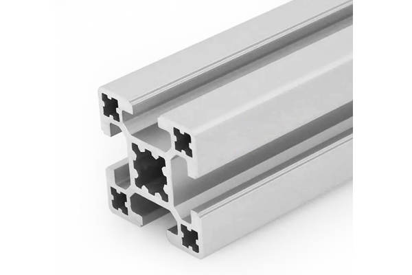
One slot system at a 40 mm pitch, across six section families. At 40 x 40 there are three variants that look similar and behave very differently: a single-slot section with three solid faces, a four-slot section, and an eight-slot section with two slots per face. Above that come the rectangular beams at 40 x 80, 40 x 120 and 40 x 160, each with a standard and a heavy wall version at the larger two sizes.
The slot pitch and the 8 mm mouth are common to all of them, so one accessory range covers the whole series. That is the practical value of staying inside one series even when the sections differ.
| Section | Slots | Weight | Slot detail |
|---|---|---|---|
| 40 x 40 single | 1 | 2.10 kg/m | 10.2 mm groove, 8 mm mouth, three solid faces |
| 40 x 40 four slot | 4 | 1.30 to 2.35 kg/m | M6 slot, 8 mm mouth, 30 mm pitch |
| 40 x 40 eight slot | 8 | 1.70 kg/m | Two per face, 10 mm between centres, M6 |
| 40 x 80 heavy | 6 | 3.60 kg/m | 2 per long face, 1 per short face, 40 mm pitch |
| 40 x 120 | 8 | 4.60 kg/m | 40 mm pitch, outer pair 80 mm apart, M8 |
| 40 x 120 heavy | 8 | 5.40 kg/m | Same layout, thicker wall |
| 40 x 160 | 10 | 5.80 kg/m | 40 mm pitch, outer pair 120 mm apart, M8 |
| 40 x 160 heavy | 10 | 6.60 kg/m | Same layout, thicker wall |
02Why is the eight-slot 40 x 40 weaker than the four-slot?
Because eight slots in the same 40 mm envelope removes more material than four. The eight-slot section is 1.70 kg/m against the four-slot’s 1.30 to 2.35, and the wall between two adjacent slots on the same face is only about 2 mm. The estimated second moment about either axis drops to roughly 4.5 cm4, against about 7 cm4 for a four-slot at 2.0 kg/m.
So the eight-slot is not a stronger four-slot. It is a four-slot with twice the fixing positions and less than two thirds of the stiffness. That is a legitimate trade for a frame that carries panels and cables, and a bad one for a frame that carries load.
40 x 40 four slot
- About 7 cm4 estimated, 1.30 to 2.35 kg/m
- Four fixing faces, one slot each
- The general purpose default
- Stiffer per kilogram than the eight slot
40 x 40 eight slot
- About 4.5 cm4 estimated, 1.70 kg/m
- Eight slots, two per face, 10 mm apart
- More fixing positions and cable routes
- Weaker in bending than the four slot it resembles
03When is the single-slot section the right choice?
When the load path runs through solid metal rather than through a slot. The single-slot 40 x 40 has one 10.2 mm slot and three solid faces, at 2.10 kg/m. Those three faces are flat, uninterrupted and available for mounting a rail, a linear guide or a machined bracket, and there is no slot opening to distort under a bolt.
It is the section for a guide rail base, a carriage, or a member where a face has to stay flat for a running surface. It is a poor choice for a frame corner, because a corner needs slots on two adjacent faces.
- Single slot: rail bases, carriages, machined brackets, anywhere a solid face matters.
- Four slot: general framing, corners, guards, workbenches. The default.
- Eight slot: panel-heavy frames, cable routing, many small fixings, low load.
- Rectangular 40 x 80 and above: spans and loads, where the depth does the work.
04How does the moment of area step up through the range?
The numbers below are estimated on a 2.5 mm nominal wall with the slot openings deducted approximately, and they are what the selection actually turns on. Note that the step from 40 x 40 to 40 x 80 is a factor of about six, and from 40 x 80 to 40 x 120 about three.
| Section | I, strong axis | Weight | I per kg |
|---|---|---|---|
| 40 x 40 four slot | approx. 7 cm4 | 2.0 kg/m | 3.5 |
| 40 x 40 eight slot | approx. 4.5 cm4 | 1.70 kg/m | 2.6 |
| 40 x 40 single slot | approx. 9 cm4 | 2.10 kg/m | 4.3 |
| 40 x 80 heavy | approx. 40 cm4 | 3.60 kg/m | 11.1 |
| 40 x 120 | approx. 110 cm4 | 4.60 kg/m | 23.9 |
| 40 x 120 heavy | approx. 130 cm4 | 5.40 kg/m | 24.1 |
| 40 x 160 | approx. 235 cm4 | 5.80 kg/m | 40.5 |
| 40 x 160 heavy | approx. 280 cm4 | 6.60 kg/m | 42.4 |
The last column is the one to read. Stiffness per kilogram rises steeply with depth, which is why a 40 x 160 at 5.80 kg/m is far more efficient as a beam than two 40 x 80 at 3.60 each, even though the two 40 x 80 weigh 7.20 kg/m together. Depth beats quantity in bending, always.
05What does the selection matrix look like by span?
For a simply supported beam with a uniform load and an L/360 limit, the spans below are the practical range for each section at a light load. Above the upper figure the deflection governs and the section has to step up.
| Section | Comfortable span | Upper span at light load | Governed by |
|---|---|---|---|
| 40 x 40 four slot | 0.6 m | 0.9 m | Deflection |
| 40 x 40 eight slot | 0.5 m | 0.7 m | Deflection |
| 40 x 40 single slot | 0.7 m | 1.0 m | Deflection |
| 40 x 80 heavy | 1.5 m | 2.0 m | Deflection |
| 40 x 120 | 2.0 m | 2.6 m | Deflection |
| 40 x 120 heavy | 2.2 m | 2.8 m | Deflection |
| 40 x 160 | 2.6 m | 3.2 m | Deflection |
| 40 x 160 heavy | 2.8 m | 3.4 m | Deflection |
Two caveats. These assume a light uniform load; a heavy machine head changes the answer and the calculation has to be done. And they say nothing about vibration: a section that passes deflection at 2 m can still sit on a machine harmonic, which is a separate check with a separate answer.
06What five numbers should be on the enquiry?
A range enquiry needs the span and the load, because that is what picks the section. Everything else is secondary.
- Span and support condition
- clear span, simply supported or braced
- Load and distribution
- uniform or point, and the magnitude
- Slot count needed
- how many fixing faces, which decides between four and eight slot
- Whether a solid face is needed
- for a rail, a guide or a machined bracket
- Finish and cut list
- mill or anodised, and the lengths
- Sections
- 40 x 40 single, four or eight slot, 40 x 80, 40 x 120, 40 x 160
Send the span, the load and the slot requirement
- 40 series, 40 x 40 four slot and 40 x 80 heavy
- Spans 1.2 m and 1.8 m, uniform load 30 kg/m
- Mixed order, 60 m of each
- Mill finish, cut to list
- Slot count noted per member, because corners need two adjacent faces
Tell us the span before the section. The step from 40 x 40 to 40 x 80 is a factor of six in stiffness, and picking the section first usually means picking it twice.
Related sections and categories
The full range is listed under 40 Series Aluminium Profiles. For span tables on the most used beam, see the 40 x 80 mm load page, and for a gantry built from 40 x 80 and 80 x 120, the pairing page.
Is the eight-slot 40 x 40 stronger than the four-slot?
No, it is weaker. Eight slots in the same envelope removes more material, so the estimated second moment drops to about 4.5 cm4 against about 7 cm4 for a four-slot at 2.0 kg/m. The eight-slot gives you twice the fixing positions and cable routes at the cost of a third of the stiffness. It is a panel frame, not a load-bearing one.
Which 40 series section should I use for a 1.5 m span?
40 x 80 heavy at 3.60 kg/m is comfortable at 1.5 m for a light uniform load, and it reaches about 2 m before deflection governs. A 40 x 40 will not do it: the deflection limit takes over well before 1 m. If the load is a machine head rather than a distributed load, run the calculation rather than the table.
Why is stiffness per kilogram so much higher on the deep sections?
Because the second moment of area rises with the cube of the depth, while the mass rises roughly linearly with the perimeter. A 40 x 160 at 5.80 kg/m has about 235 cm4, which is nearly six times a 40 x 80 at 3.60, for 1.6 times the mass. Depth is always more efficient than quantity in bending.
When would I use the single-slot 40 x 40?
When a face has to be solid and flat, such as a linear rail base, a carriage or a machined bracket mounting. It has one slot and three uninterrupted faces at 2.10 kg/m. It is a poor choice for a frame corner, because a corner needs slots on two adjacent faces.
Can I mix sections in one order?
Yes, and most orders do. The slot pitch and the 8 mm mouth are common across the series, so one accessory range covers the whole order. The minimum applies to the total length rather than to each section, and the cut list is what drives the packing.
Send the span, the load and the slot requirement
Give us the spans, how the load is distributed, and how many fixing faces each member needs. We will come back with the sections, the weights and the accessory list for the whole frame.
Request a quotationRelated Products
 40 x 40 mm Light Aluminium Profile for Mining Equipment
40 x 40 mm four-slot aluminium extrusion in 6063-T5 from 1.30 kg/m, for guards…
 Joining Plate PG40-4040
Joining plate sized for two 40 × 40 mm profiles meeting at 90°, the…
 Strut Aluminium Profile 40×40 mm 4-Slot T-Slot Extrusion Machine Frame
40 x 40 mm four-slot T-slot strut aluminium profile in 6063-T5 with M6 slots…
 Strut Aluminium Profile 20×40 mm 2-Slot T-Slot Extrusion for Light Frames
20 x 40 mm two-slot T-slot strut aluminium profile in 6063-T5 with two M6…
 Strut Aluminium Profile 30×30 mm 4-Slot Light T-Slot Extrusion
30 x 30 mm light-wall four-slot T-slot strut aluminium profile in 6063-T5 with M5…
 Strut Aluminium Profile 30×120 mm 3-Slot Wide Beam T-Slot Extrusion
30 x 120 mm three-slot wide-beam T-slot strut aluminium profile in 6063-T5 with three…
 Strut Aluminium Profile 40×40 mm 3-Slot T-Slot Extrusion Closed Face
40 x 40 mm three-slot T-slot strut aluminium profile in 6063-T5 with one solid…
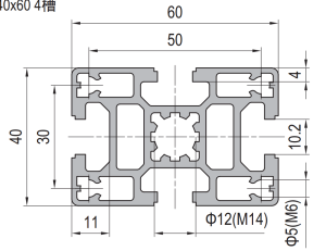 Strut Aluminium Profile 40×60 mm 4-Slot Rectangular T-Slot Extrusion
40 x 60 mm four-slot rectangular T-slot strut aluminium profile in 6063-T5 with M6…
