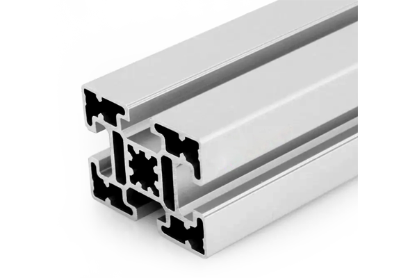
45 x 60 mm Aluminium Profile Solutions for Windows and Facades
45 x 60 mm four-slot aluminium extrusion in 6063-T5 for shopfront, screen and facade framing in the Philippines. 2.8 kg/m, AA25 anodised for coastal sites, with drainage slots machined to drawing.
| Material | Aluminium |
|---|---|
| Alloy Grade | 6063-T5 |
| Temper | T5 |
| Section Size | 45 x 60 mm, four slots |
| Slot | 4 x 10.2 mm groove, 10 mm mouth, M8; or 8 mm groove with M10 on a 33 mm pitch |
| Length | 6 m stock; cut to frame list to +/-0.5 mm |
| Tolerance | EN 755-9, wall +/-0.15 mm; straightness 1.5 mm per metre; twist 2 degrees |
| Surface | Anodised AA20 or AA25 to EN ISO 7599, sealed; clear or black |
| MOQ | 150 m |
| Lead Time | 20 to 28 days after deposit, plus 6 to 9 days ocean to Manila |
| Loading Port | Shanghai / Ningbo |
| Supply Ability | 600 t per month extrusion with in-house anodising |
| Payment Terms | T/T 30% deposit + 70% before shipment | L/C at sight |
| Trade Terms | FOB | CIF | DAP Manila |
| Certifications | Mill certificate per heat, coating thickness and seal report per lot, salt spray to EN ISO 9227 on request, RoHS and REACH declarations |
01What does a water tightness test actually measure?
Not whether water touches the inside face. It measures whether water crosses the inner plane of the assembly while a pressure difference is applied to the outside and water is sprayed at a defined rate. Under ASTM E331 the usual arrangement is a static pressure of 20 percent of the design wind pressure, with a minimum around 300 Pa, a spray rate of about 3.4 litres per minute per square metre, held for 15 minutes.
The distinction matters because a frame can be wet inside and still pass. What the test looks for is water reaching the interior plane, which is a different question from whether water got past the outer seal. That is the whole logic of drained construction: let water in, then lead it out before it reaches the inner line.
| Standard | Method | Typical test condition |
|---|---|---|
| ASTM E331 | Static pressure, spray rack | 20 percent of design pressure, minimum 300 Pa, 15 minutes |
| AAMA 501.1 | Dynamic pressure, aircraft propeller | Same pressure, with gusting |
| AAMA 501.2 | Hose test on installed units | Field check of a specific detail |
| AAMA 501 | Structural performance | Design pressure at 1.5 times, deflection measured |
02Why is a drain hole not the same as pressure equalisation?
A drain hole lets water out. It does nothing about the pressure difference across the inner seal, and that pressure difference is what pushes water in. If the chamber behind the outer gasket is sealed, water accumulates there and the pressure on both sides of the inner gasket is the same as the outside, so the inner gasket sees the full wind pressure and leaks.
Pressure equalisation is a different arrangement: the chamber behind the outer gasket is vented to the outside, so the pressure in the chamber tracks the outside pressure and the differential across the inner seal falls to nearly zero. The drain then removes whatever water got in, at low pressure, which is a much easier job.
- The vent area should be at least equal to the drain area, and preferably larger. A system with big drains and small vents does not equalise.
- The chamber needs depth, typically 5 mm or more, so it can hold the transient water without bridging to the inner seal.
- The inner seal should be continuous and on the warm side, so it is not the primary barrier against driving rain.
- Drain slots must not be blocked by the gasket when it compresses. Check the compressed gasket section, not the free one.
03How do NSCP wind speeds translate to a test pressure?
Through the velocity pressure, q equals 0.613 times the wind speed in metres per second squared, which gives pascals. For a basic wind speed of 250 kilometres per hour, that is 69.4 metres per second, and q is about 2,950 Pa. That is the velocity pressure, not the design pressure on a facade.
The design pressure applies pressure coefficients: roughly 0.8 outward on a windward wall and up to minus 1.5 at corners and edges, where suction governs. So a facade designed to 2,950 Pa velocity pressure sees a design pressure in the region of 2,300 to 2,400 Pa on the field of the wall, and considerably more at the corners. The water test pressure is then 20 percent of that.
| Basic wind speed | Velocity pressure | Design pressure, field of wall | Water test at 20 percent |
|---|---|---|---|
| 150 kph | 1,060 Pa | About 850 Pa | 300 Pa minimum applies |
| 200 kph | 1,890 Pa | About 1,510 Pa | About 300 Pa |
| 250 kph | 2,950 Pa | About 2,360 Pa | About 470 Pa |
| 300 kph | 4,250 Pa | About 3,400 Pa | About 680 Pa |
Corner and edge zones can see coefficients of minus 1.5 or more, so the local design pressure there is roughly twice the field value. A test on a typical unit does not cover the corner detail, which is why corner mock-ups matter on a tall facade.
04Is a 45 x 60 T-slot section a window system?
No, and it is worth being direct about that. A proprietary window system has gasket grooves, a thermal break and a drainage chamber built into the extrusion. A 45 x 60 T-slot section is a structural frame: it carries the glass, it takes a separate bead, and the gasket line and drainage path have to be created by the assembly detail.
That is not a criticism of the section. For shopfronts, screens, secondary glazing and facade supports it works well, because those assemblies are usually built with a separate bead and a machined drainage path anyway. What it will not do is replace a purpose-made window profile on a high-rise unitised facade, and a supplier who claims otherwise is selling you a problem.
45 x 60 T-slot framing
- Structural, 2.8 kg/m, four 10.2 mm slots
- Takes a separate glazing bead and a machined drainage path
- Good for shopfronts, screens, secondary glazing
- Reconfigurable on the slot pattern
Proprietary window system
- Gasket grooves and drainage chamber in the extrusion
- Thermal break available, which a T-slot cannot offer
- Designed and tested as a system
- Not reconfigurable, and tied to one supplier’s accessories
05What happens at the coast with stainless fixings?
A galvanic couple forms, and the aluminium is the anode. Stainless steel is cathodic to aluminium in a chloride environment, so at every stainless fastener in contact with the frame, the aluminium around the fastener corrodes preferentially. The visible result is a white salt bloom around the fixing and pitting of the frame, and the structural result is a hole that grows.
The fix is isolation, not a different stainless grade. A nylon or EPDM washer under the head, a sleeve in the hole, and a sealant barrier at the interface all break the electrical path. It is cheap at the design stage and awkward to retrofit.
Coastal fixing checklist
- Isolate every stainless-to-aluminium contact with a washer and a sleeve, not just one.
- Specify a sealant that is neutral cure; acetoxy silicone releases acid that attacks the anodic film.
- Keep the frame washed. Chloride accumulates in the slot and the drain, and a periodic fresh water rinse is more effective than a thicker coating.
- Avoid trapping water in the slot with a cover that has no drain path of its own.
- Check the coating class: AA20 minimum, AA25 within a kilometre of the shore.
06What five numbers should be on the enquiry?
A facade enquiry is a performance enquiry. Give the performance and the section follows.
- Location and wind zone
- the NSCP basic wind speed for the site, not the city name
- Water test requirement
- ASTM E331 or AAMA 501.1, and the pressure to be held
- Glass and span
- thickness and panel size, because the span check needs both
- Coating class
- AA20 or AA25 depending on distance from the shore
- Assembly type
- shopfront, screen, secondary glazing or facade support, because they drain differently
- Section
- 45 x 60 mm at 2.8 kg/m, or 45 x 90 at 4.10 kg/m for taller panels
Send the wind zone and the water test requirement
- 45 x 60 mm, 6063-T5, four 10.2 mm slots, 2.8 kg/m
- Cut to the frame list, drainage slots machined to drawing
- AA25 anodised, clear
- Water test to ASTM E331 at 470 Pa
- Isolating washers and sleeves supplied with the fixings
Tell us the distance to the shore. Within a kilometre the coating class changes and the fixing isolation stops being optional, and both of those are cheaper to specify than to discover after the first wet season.
Related sections and categories
The 45 x 60 is listed under 45 Series Aluminium Profiles, and the 45 x 90 mm six slot section at 4.10 kg/m covers taller panels. For outdoor structures rather than windows, the typhoon-zone frame page covers wind load on freestanding frames.
Can a 45 x 60 T-slot profile be used as a window frame?
For shopfronts, screens and secondary glazing, yes, with a separate glazing bead and a machined drainage path. For a unitised high-rise facade, no: a proprietary system has gasket grooves, a drainage chamber and often a thermal break built into the extrusion, and a T-slot section has none of those. It is a structural frame, and it should be sold as one.
Why does the frame leak even though there are drain holes?
Because drain holes remove water but do not equalise pressure. If the chamber behind the outer gasket is sealed, the inner seal sees the full wind pressure and water is pushed through it. Venting the chamber to the outside drops the differential across the inner seal to nearly zero, and the drain then has an easy job.
What test pressure should I specify for a Philippine project?
Twenty percent of the design wind pressure, with a minimum of about 300 Pa. For a basic wind speed of 250 kilometres per hour the velocity pressure is about 2,950 Pa and the design pressure on the field of the wall is roughly 2,360 Pa, so the water test is around 470 Pa. Corner zones see roughly twice the field pressure and are usually tested on a separate mock-up.
Which anodising class for a coastal site?
AA25 within about a kilometre of the shore, AA20 further inland. Thickness matters less than the seal, so ask for the seal test as well. And keep the frame washed: chloride accumulates in the slot and the drain, and a periodic fresh water rinse does more than a thicker coating.
Why does the aluminium corrode around stainless screws?
Because stainless is cathodic to aluminium in a chloride environment, so the aluminium becomes the anode and corrodes preferentially at the contact. The fix is isolation: a washer under the head, a sleeve in the hole and a sealant barrier. A different grade of stainless does not solve it, because the couple exists between the two metals rather than within the stainless.
Send the wind zone and the water test requirement
Give us the NSCP wind speed for the site, the water test standard and pressure, and the distance to the shore. We will come back with the section, the coating class and the drainage detail.
Request a quotationRelated Products
 40 x 40 mm Light Aluminium Profile for Mining Equipment
40 x 40 mm four-slot aluminium extrusion in 6063-T5 from 1.30 kg/m, for guards…
 Custom 45 x 90 mm Aluminium Extrusion: Dies, Tooling and Lead Time
45 x 90 mm six-slot aluminium extrusion in 6063-T5 from a China plant. 4.10…
 T-Slot Reducing Profile
Reducing insert that narrows a wide T-slot to accept standard nuts and accessories from…
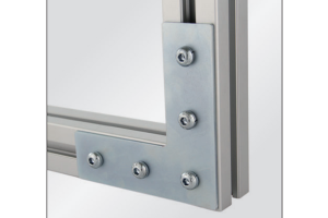 Joining Plate PG45-4545
Joining plate for two 45 × 45 mm profiles at 90°, sized to the…
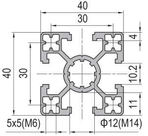 Strut Aluminium Profile 40×40 mm 4-Slot T-Slot Extrusion Machine Frame
40 x 40 mm four-slot T-slot strut aluminium profile in 6063-T5 with M6 slots…
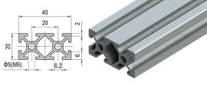 Strut Aluminium Profile 20×40 mm 2-Slot T-Slot Extrusion for Light Frames
20 x 40 mm two-slot T-slot strut aluminium profile in 6063-T5 with two M6…
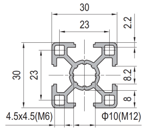 Strut Aluminium Profile 30×30 mm 4-Slot Light T-Slot Extrusion
30 x 30 mm light-wall four-slot T-slot strut aluminium profile in 6063-T5 with M5…
 Strut Aluminium Profile 30×120 mm 3-Slot Wide Beam T-Slot Extrusion
30 x 120 mm three-slot wide-beam T-slot strut aluminium profile in 6063-T5 with three…
