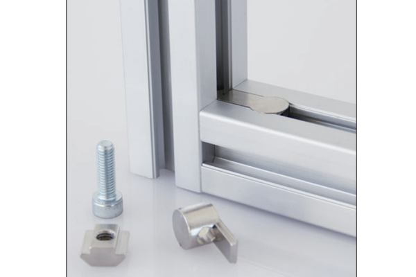
Butt Connector
Connector that joins two profiles end to end in a straight line, transmitting bending and shear across the butt joint so the members behave as one.
| Material | Zinc-plated steel or stainless bar; aluminium plate |
|---|---|
| Alloy Grade | 6063-T5 on plate versions |
| Temper | custom |
| Section Size | Fits the core hole or slot of 30-60 series profiles |
| Slot | Access hole Ø9-Ø12 mm; plate bolts M8-M10 |
| Length | Bar 80-140 mm; plate 80-120 mm |
| Tolerance | ±0.15 mm on bar diameter and plate holes |
| Surface | Zinc plated; anodised or powder coated plate |
| MOQ | 300 |
| Lead Time | 15-25 days after deposit |
| Loading Port | Shanghai / Ningbo |
| Supply Ability | 120,000 pcs per month |
| Payment Terms | T/T 30% deposit + 70% before shipment | L/C at sea |
| Trade Terms | FOB | CIF | EXW |
| Certifications | ISO 9001:2015 | ISO 14001 | RoHS | REACH |
Connecting elements · In-line joint
A butt connector joins two profiles end to end in a straight line. The two members meet face to face and the connector carries the load across that joint, so the two pieces behave as one continuous member.
An in-line joint is a different problem from a corner joint, and it is worth understanding why. At a corner the two members meet at an angle and the joint resists rotation; at a butt joint the members are in line and the joint has to transmit bending and shear straight through. A butt joint is therefore weakest exactly where a continuous member is strongest — at the neutral axis — because the connector has to bridge the two faces without a continuous section.
Why a butt joint needs a connector at all
Two profiles pushed together end to end will hold in compression and nothing else. Any bending, any tension, any shear and the joint opens. That is why a butt connector exists: it is the part that turns two members into one by carrying the loads the plain faces cannot.
The connector works by being fixed into both members and bridging the joint. A bar connector sits inside the core hole and is pulled tight by a screw; a plate connector sits on the outside face and is bolted into the slot of both members. The bar version leaves a clean face, the plate version is easier to fit and to take apart.
- Cut both members square A butt joint magnifies a cutting error: the two faces have to meet over their whole area, so both cuts have to be square to within 0.2 mm.
- Deburr the ends A burr holds the faces apart and puts the whole load onto the connector instead of the joint. Deburr both ends before assembly.
- Fit the connector to the first member Insert the bar into the core hole, or bolt the plate to the slot of the first member, leaving the connection to the second member accessible.
- Bring the members together Slide the second member onto the connector until the faces meet. Check that the slots line up along the member.
- Tighten and check straightness Tighten the connecting screws and check that the two members are straight. A slight misalignment at a butt joint shows as a kink over the length of the member.
- Reinforce if the joint carries bending Where the joint is in a span rather than at a support, add a splice plate on the opposite face to raise the bending capacity.
| Connector | Face | Bending capacity | Drilling | Removable |
|---|---|---|---|---|
| Internal bar | Clean | High | Yes, access hole | Difficult |
| External plate, one face | Visible | Moderate | No | Easy |
| Splice plate, two faces | Visible both | High | No | Easy |
| Half-lap | Flush | Moderate | Machined ends | Difficult |
Practical point: put a butt joint where the member is supported, not in the middle of a span. A joint at a support carries almost no bending moment, so the connector only has to hold the members in line. The same joint in mid-span has to carry the full bending moment, which needs a much heavier connector.
Frequently asked questions
Where should a butt joint be placed?
At a support rather than mid-span, wherever the design allows. At a support the joint carries almost no bending and any of the connectors will do; in mid-span it carries the full moment and needs a splice plate or a heavier connector.
Will a butt joint be as strong as a continuous member?
No, and it should not be assumed to be. A bolted butt joint is typically less stiff than the continuous member, so where the joint falls in a span the design should account for the reduced stiffness.
Do I need a plate on both faces?
Where the joint carries a bending moment, yes — a plate on each face puts the connector in tension and compression and raises the capacity substantially.
Can a butt joint be hidden?
Yes, with an internal bar connector or a half-lap joint. Both need the members prepared, so they are a drawing decision rather than a site one.
What about the slots lining up?
The connector should be fitted so the slots of the two members line up along the length. On a bar connector this happens naturally; on a plate connector check it before final tightening.
Send the member length and where the joint falls
Tell us the member length and where the joint has to be. We will recommend the connector type, the placement and the reinforcement, and return FOB pricing within one working day.
Request a QuoteRelated Products
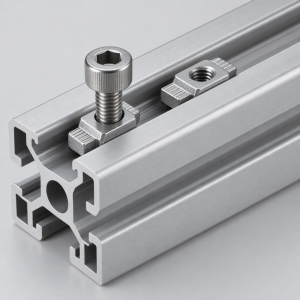 T-Nut for 10 mm Aluminium Profiles M4 M5 M6 M8 M10
Full range of T-slot nuts from M4 to M10 for 15 to 60 series…
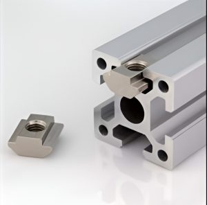 Pre-set T-Slot Nut for 8 mm Aluminium Profiles M5 M6 M8
Pre-set T-slot nut with anti-drop spring tab for 20, 30 and 40 series aluminium…
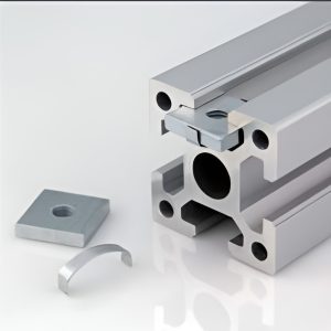 Square Nut for 8 mm T-Slot Aluminium Profiles M5 M6 M8
Square T-slot nut with four flat sides for 30 and 40 series aluminium profiles.…
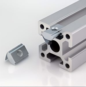 Subsequent Nut for 8 mm T-Slot Aluminium Profiles M5 M6 M8
Subsequent T-slot nut for 30 and 40 series aluminium profiles. M5, M6 and M8…
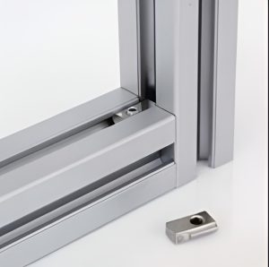 Anti-torsion Subsequent Nut for 8 mm T-Slot Aluminium Profiles
Anti-torsion subsequent T-slot nut with twin wings for 30 and 40 series aluminium profiles.…
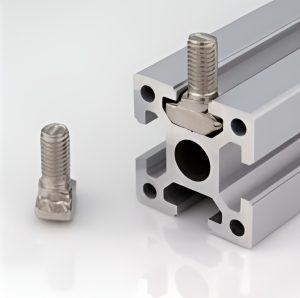 T-Bolt for 8 mm T-Slot Aluminium Profiles M6 M8 M10
T-bolt with integral T-head for 20, 30 and 40 series aluminium profiles. M5, M6,…
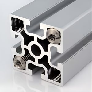 Hole Reducer Bolt for 8 mm T-Slot Aluminium Profiles
Hole reducer bolt with stepped M8 to M6 thread for 30 and 40 series…
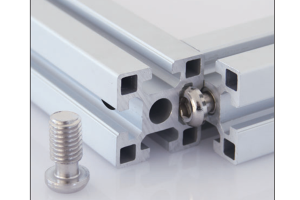 Screw Type Anchor Connector Aluminium Profile Hidden Joint Fastener 30 40 mm Series
Screw type anchor connector for aluminium profile giving a hidden joint with no visible…
