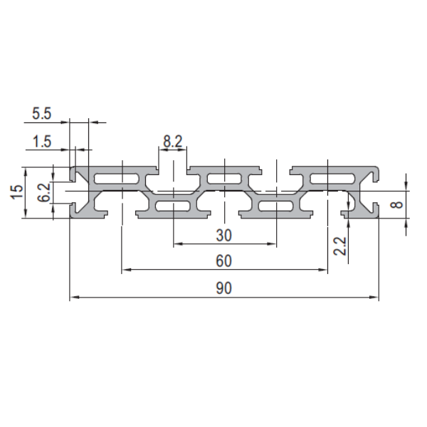
PG30 90 x 15 mm Seven Slot Aluminium Strut Profile Narrow Multi Slot Rail
90 x 15 mm seven-slot aluminium strut profile with 8.2 mm grooves on a staggered 30 mm pitch. Dedicated cable and pneumatic routing rail for machine frames, using M8 fasteners.
| Material | Aluminium |
|---|---|
| Alloy Grade | 6063-T5 |
| Temper | T5 |
| Section Size | 90 x 15 mm |
| Slot | 7 x 8.2 mm groove, 6 mm mouth, staggered, 30 mm pitch, M8 |
| Length | 6 m stock, cut to drawing to +/-0.5 mm |
| Tolerance | EN 755-9 / GB/T 6892, wall +/-0.15 mm |
| Surface | Mill finish / clear anodised / black anodised |
| MOQ | Made to order; small trial lengths available from stock offcuts |
| Lead Time | Typically 2 to 3 weeks for mill finish, about a week longer for anodising |
| Loading Port | Shanghai, Ningbo, Qingdao |
| Supply Ability | Extrusion capacity for standard and custom dies, with in-house cutting, machining and anodising |
| Payment Terms | T/T 30 per cent deposit, balance against copy of bill of lading; L/C at sight for larger orders |
| Trade Terms | FOB, CIF, CFR, EXW |
| Certifications | Mill certificate to EN 10204 3.1 on request, RoHS and REACH declarations |
01What is the 90 x 15 mm seven slot profile?
Why seven slots on a 15 mm thick section?
Because this profile is not a beam. It is a dedicated cable and pneumatic routing rail, designed to be mounted on the side or back of a machine frame. The 90 mm width gives room for seven 8.2 mm grooves on a staggered 30 mm pitch, and the 15 mm thickness keeps the section light (0.62 kg/m). Each slot carries a cable clip, a pneumatic fitting or a sensor wire, isolated from the others.
Is it load-bearing?
No, or at least not intentionally. The 15 mm thickness gives a very low second moment of area in bending, about 0.3 cm4 on the strong axis. It is meant to be bolted to a frame member, not to span between supports. If it has to span, keep the distance under 300 mm or use a thicker section.
What fasteners fit the 8.2 mm groove?
M8 slot nuts, T-bolts and cover strips from the 30 series range. The 8.2 mm groove is the same as the standard 30 series, so all 30 series accessories fit.
02Section data
| Item | Value | Note |
|---|---|---|
| Envelope | 90 x 15 mm narrow rectangular | width 90 mm, thickness 15 mm |
| Slots | 7 | 8.2 mm groove, 6 mm mouth, staggered |
| Slot pitch | 30 mm staggered | alternating upper and lower |
| Central bore | none typically | this is a routing rail, not a tie member |
| Wall | approx. 2.0 mm at slot lip | 30 series standard wall |
| Weight | approx. 0.62 kg/m | from published specification |
| Alloy | 6063-T5 | EN AW-6063 |
| Standard | EN 755-9 / GB/T 6892 | wall tolerance +/-0.15 mm |
| Length | 6 m stock | cut to drawing to +/-0.5 mm |
03Cable capacity: how much fits in seven slots
The whole point of this profile is cable routing density. Seven 8.2 mm grooves give seven independent channels, each of which can carry a cable clip or a pneumatic fitting. The capacity depends on the cable diameter and the clip type.
| Slot | Typical cable diameter | Typical content |
|---|---|---|
| Slot 1 | 3 to 6 mm | signal wires (sensors, encoders) |
| Slot 2 | 6 to 8 mm | power cables (24 V DC) |
| Slot 3 | 8 to 12 mm | power cables (230 V AC) |
| Slot 4 | 6 to 8 mm | pneumatic tubing (4 to 6 mm OD) |
| Slot 5 | 3 to 6 mm | signal wires (actuators, solenoids) |
| Slot 6 | 8 to 12 mm | power cables (motor drives) |
| Slot 7 | 3 to 6 mm | earth and shield wires |
With this assignment, one rail carries the equivalent of a 25 mm x 50 mm cable trunk, but without the enclosure. Cables are accessible for inspection and modification without removing a cover.
- Separated power and signal: signal slots are isolated from power slots by the staggered pitch, reducing crosstalk.
- Pneumatic routing: one or two slots carry 4 to 6 mm OD pneumatic tubing with push-in fittings.
- Earth and shield: a dedicated slot for earth wires keeps grounding separate from signal and power.
04How the staggered pitch works
The seven slots are not all in a single row. They are staggered: alternate slots sit at slightly different heights within the 15 mm thickness. This allows the grooves to overlap in plan view without the slot mouths intersecting, which is how you fit seven 8.2 mm grooves into a 90 mm width.
The staggered layout also means that cable clips in adjacent slots do not touch each other, which prevents chafing between cables of different voltages. The downside is that the profile has a top and bottom: the staggered pattern is not symmetric, so the rail must be oriented correctly when mounted.
05Why not use a standard cable trunk instead?
Choose the seven-slot rail
- You need separated channels for power, signal and pneumatic lines
- Cables need to be accessible for inspection without removing a cover
- The frame already uses 30 series T-slot profiles and the rail is compatible
- Pneumatic fittings need to be mounted along the cable run
- The frame is compact and an external trunk would be too bulky
Choose a standard cable trunk
- You need full enclosure to meet IP rating or cable protection requirements
- The cable run is long and straight with no need for branching
- EMC shielding is required: a metal trunk provides it, the rail does not
- The frame does not use T-slot profiles and the rail would be an oddity
- Cost is the primary driver: a plastic trunk is cheaper per metre
06Mounting the rail to the frame
The rail is mounted to the frame using the same 8.2 mm grooves it carries cables in. Typically, one or two slots are dedicated to mounting brackets that bolt the rail to a 30 or 40 series frame member. The remaining five or six slots carry cables.
If all seven slots are needed for cables, the rail can also be mounted from behind using through-bolts that pass through the 15 mm thickness into tapped holes on the frame. This is less common because it requires machining the back face, but it frees all seven slots for cable use.
07Failure modes to design out
| What goes wrong | Why it happens | Design it out by |
|---|---|---|
| Rail deflects under its own weight plus cables | the 0.3 cm4 second moment of area is very low | support the rail every 300 mm, or mount it on a frame member |
| Cable clip pulls out of the groove | the 2.0 mm wall at the lip limits pull-out to about 0.8 kN | use clip types that grip the groove, not push-in types, for heavier cables |
| Pneumatic tubing chafes against adjacent slot lip | the staggered pitch brings adjacent grooves close | use foam separators or route tubing in the upper stagger only |
| Rail is mounted upside down | the staggered pattern is not symmetric | mark the top face on the drawing and at installation |
| Power cables induce noise in signal slots | adjacent slots have no EMC barrier | put a grounded earth wire in the slot between power and signal slots |
08What to check before you order
Procurement checklist for the seven-slot cable rail
- Confirm the slot assignment: which slots carry power, signal, pneumatic and earth. Put it on the drawing.
- Confirm the orientation: the staggered pattern has a top and bottom. Specify which way up.
- Confirm the mounting method: which slots are used for brackets, or whether through-bolts are needed on the back face.
- Confirm the support spacing: the rail needs support every 300 mm if it is not backed by a frame member.
- Confirm the finish: mill for hidden use, anodised for exposed service.
- Confirm the quantity in metres. A 6 m bar yields ten 580 mm rails.
09Terms used on this page
- Staggered pitch
- A slot layout where alternate grooves are at different heights, allowing more slots to fit in a given width.
- Cable rail
- A profile whose primary function is routing cables along a frame, not carrying structural load.
- Cable trunk
- An enclosed channel for cables, typically plastic or metal, that provides protection and EMC shielding.
- Pull-out force
- The force to pull a slot nut or clip out of the groove. The 2.0 mm wall gives about 0.8 kN for an M8 nut.
- EMC barrier
- A conductive barrier between cables that reduces electromagnetic interference. The rail does not provide one; a metal trunk does.
10Questions buyers ask
Can I use standard 30 series accessories in the seven-slot rail?
Yes. All seven slots use the same 8.2 mm groove as the standard 30 series, so M8 slot nuts, T-bolts, cable clips and cover strips all fit.
Is it load-bearing?
No. It is a cable routing rail. The 15 mm thickness gives a very low second moment of area. Mount it on a frame member or support it every 300 mm.
How many cables can it carry?
Seven slots, each carrying one to three cables depending on diameter. A typical assignment carries 10 to 15 cables across power, signal, pneumatic and earth, equivalent to a 25 x 50 mm cable trunk.
What is the staggered pitch for?
It lets seven 8.2 mm grooves fit in 90 mm of width without the slot mouths intersecting. It also isolates cables in adjacent slots to prevent chafing.
What is the weight per metre?
Approximately 0.62 kg/m, from the published product specification.
Can it be anodised?
Yes. Clear, black, champagne and bronze at 10 to 15 micron. Anodising is recommended for exposed service to prevent oxide staining on cables.
What we need to quote this section
- The section drawing or the profile reference GP-SP-9015-7S.
- The cut length for each rail and the number of rails.
- The slot assignment if you want it called out on the drawing.
- The orientation (top face) if the staggered pattern matters.
- The finish: mill, clear anodised, or a specified colour.
- Any certification requirement: mill certificate to EN 10204 3.1.
Send those six items and the quotation comes back with the extrusion price, the cutting charge, the finish surcharge and the lead time broken out separately. Browse the full aluminium profile catalogue and the 30 series aluminium profiles range for related sections.
Need this cable routing rail quoted for your machine frame?
Send the section, the cut list, the slot assignment and the finish. We quote extrusion, cutting and anodising as separate lines.
Request a quotationRelated Products
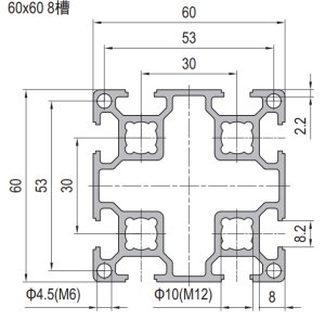 PG30 60×60 mm Eight Slot Aluminium Strut Profile Heavy Duty T-Slot Extrusion for Robot Pedestals
60 x 60 mm eight slot PG30 heavy duty aluminium strut profile in 6063-T5…
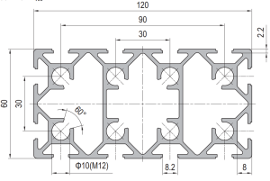 PG30 120 x 60 mm Twelve Slot Aluminium Strut Profile Heavy Frame Beam
A 120 x 60 mm twelve slot PG30 aluminium strut profile at about 5.20…
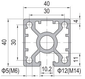 PG40 40 x 40 mm Single Slot Aluminium Strut Profile Guide Rail Base
40 x 40 mm single-slot aluminium strut profile with one 10.2 mm groove on…
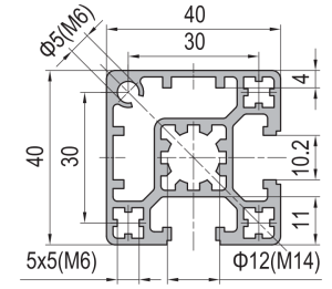 PG40 40 x 40 mm Two Slot Type A Aluminium Strut Profile Guide Rail
40 x 40 mm Type A two slot asymmetric PG40 aluminium strut profile in…
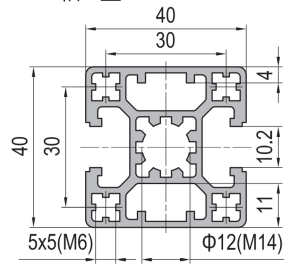 PG40 40 x 40 mm Two Slot Type B Aluminium Strut Profile Opposite Rail
40 x 40 mm Type B two-slot aluminium strut profile with two 10.2 mm…
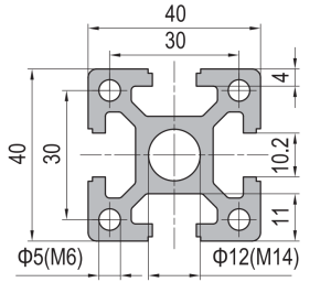 PG40 40 x 40 mm Four Slot Heavy Aluminium Strut Profile Standard Frame
40 x 40 mm heavy-wall four-slot aluminium strut profile with 10.2 mm grooves, 8…
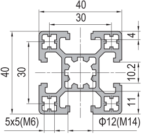 PG40 40×40 mm Four Slot Light Wall Aluminium Strut Profile Cost Optimised T-Slot Extrusion
40 x 40 mm four slot light wall PG40 aluminium strut profile in 6063-T5…
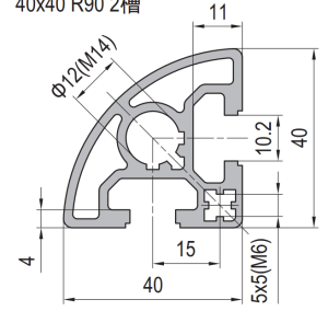 PG40 40×40 mm R90 Quarter Round Aluminium Strut Profile Radius Corner Guard Frame Extrusion
40 x 40 mm R90 quarter round PG40 aluminium strut profile in 6063-T5 with…
