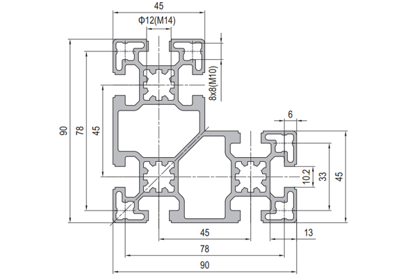
PG45 90×90 mm L-Shape Eight Slot Aluminium Strut Profile Corner Column for Frames
A 90 x 90 mm L-shaped eight slot PG45 aluminium strut profile with two 45 mm arms. For frame corners that need flush outer faces, no external fasteners and one member instead of two.
| Material | Aluminium |
|---|---|
| Alloy Grade | 6063-T5 |
| Temper | T5 |
| Section Size | 90 x 90 mm L, arms 45 mm |
| Slot | 8 x 10.2 mm groove, 10 mm mouth, 45 mm pitch |
| Length | 6 m stock, cut to drawing to +/-0.5 mm, mitre to 45 degrees on request |
| Tolerance | EN 755-9 / GB/T 6892, wall +/-0.15 mm |
| Surface | Mill finish / clear anodised / black anodised |
| MOQ | 150 |
| Lead Time | 22-32 days after deposit for mill finish |
| Loading Port | Shanghai / Ningbo |
| Supply Ability | 200 t per month |
| Payment Terms | T/T 30% deposit + 70% before shipment | L/C at sight |
| Trade Terms | FOB | CIF | EXW |
| Certifications | ISO 9001:2015 | EN 755-9 | RoHS | REACH |
Structural framing · PG45 corner section
A PG45 90 x 90 mm L-shaped aluminium strut profile is a corner section: two 45 mm arms meeting at a square outer corner, with the inner corner relieved and braced by a diagonal web. It carries eight 10.2 mm slots on a 45 mm pitch, 8 x 8 mm corner holes tapped M10 and a Ø12 mm bore tapped M14. The flange is 6 mm and the web 13 mm, the inner faces of the two outer flanges sit 78 mm apart, and the section weighs about 5.6 kg/m. It is supplied in 6063-T5, cut and mitred to order.
The reason to use an L section is the corner itself. Where two square columns meet at 90 degrees, the outside of the joint has to be closed somehow — normally with a corner bracket, an angle plate or a pair of gussets, all of which put fasteners on the outside face. An L section does the same job with the corner already in the extrusion. The two outer faces come off the die square to each other, there is nothing bolted on the outside, and the frame corner is one member instead of two.
The corner is where a frame gets expensive
Count the parts at the corner of a bolted frame and the L section usually wins on arithmetic alone. Two square columns need a bracket, a set of bolts through that bracket, and a decision about which member the bracket belongs to. An L section needs neither, because the two directions are the same piece of metal.
The comparison below is for the outside corner of a guard, an enclosure or a machine frame in the 45 series, using the same 90 mm envelope in both cases.
| Two 90 x 90 mm square columns | One 90 x 90 mm L section | |
|---|---|---|
| Members at the corner | Two | One |
| Corner brackets | One, plus its fixings | None |
| Fasteners on the outer face | 4 to 6 visible heads | None |
| Outer faces square to each other | Set by the bracket and the assembly | Set by the extrusion die |
| Joints at the corner | Two bolted joints | One mitre or butt joint |
| Corner resistance to racking | Bracket in bending and shear | Continuous arm plus a diagonal web |
| Slots available inside the corner | Slots on four faces of each column | Slots on the outer and inner faces of both arms |
The last line matters more than it looks. Two columns give you a lot of slots buried in a small volume, most of them inaccessible once the bracket is on. The L section spreads its eight slots around the outside of the corner and along the two inner faces, which is where panels, guards and infill actually need to land.
The outer corner is extruded, not assembled. Both outer faces come off the same die, so the 90 degree relationship between them is a die dimension rather than an assembly tolerance. That is the part of the corner that does not drift when the frame is re-tightened or re-shimmed.
What the diagonal web is doing
Look at the section and the inner corner is not a plain right angle: there is a diagonal web running from the inner face of one arm to the inner face of the other. It converts the corner from a bend into a triangle.
A plain L corner resists a racking load by bending the two arms at the corner. A braced corner resists it by putting the diagonal into tension or compression, which is a far stiffer load path for the same amount of metal. This is the same argument as a gusset in a welded frame, except that here it costs no extra parts and no welding.
Fitting it the right way round
An L section is not symmetric, and that has a practical consequence: its centroid does not sit at the centre of the 90 x 90 envelope, so the section has two different second moments of area about its two principal axes. The stiff direction is the one that puts the long leg in line with the bending.
On this section the centroid sits roughly 26 mm in from each outer face, not at 45 mm. In plain terms: an L is stiff when the load tries to close or open the angle, and noticeably softer when the load tries to bend the whole section about the axis that runs along the outside of one arm.
| Orientation | Stiff about | Use it for |
|---|---|---|
| Corner on the outside of the frame | The diagonal, through both arms | Frame corners and posts taking racking loads |
| One arm horizontal, one vertical, load on the horizontal arm | The horizontal arm, as a beam | Shelving and platform edges |
| Both arms vertical, load sideways | The weaker principal axis | Only where the load is small — this is the soft direction |
| Corner pointing inwards | Same as above, mirrored | Inside corners of a closed frame |
If a frame corner is going to see a significant load in one particular direction, the useful check is not the section’s headline stiffness but which way the arms are pointing relative to that load. Rotating the section 90 degrees changes the answer completely, and it costs nothing.
40 series or 45 series for the corner
There is a 40 series L section on the same 80 x 80 mm envelope, and the choice between it and this one follows the same logic as the square columns: it comes down to the joint rather than the member.
| 40 series 80 x 80 mm L | 45 series 90 x 90 mm L | |
|---|---|---|
| Envelope | 80 x 80 mm | 90 x 90 mm |
| Arm thickness | 40 mm | 45 mm |
| Slot pitch | 40 mm | 45 mm |
| Slot mouth | 8 mm | 10 mm |
| Corner hole | 5 mm round, tapped M6 | 8 x 8 mm, tapped M10 |
| Centre bore | Ø12 mm, tapped M14 | Ø12 mm, tapped M14 |
| Wall | 4 mm flange / 11 mm web | 6 mm flange / 13 mm web |
| Weight | approx. 3.40 kg/m | approx. 5.60 kg/m |
| Slot torque ceiling | approx. 15 N m for M8 | approx. 30 N m for M10 |
The 45 series corner is the one to specify when the corner joint carries the load. Its M10 corner holes take roughly double the tightening torque of the 40 series M6 holes, and the corner of a frame is exactly where the joint is asked to do the most work. If the corner is only keeping a panel in place, the 40 series section is lighter and cheaper and will do the job.
Specifying an L corner
- Decide which corner of the frame it is An L section suits an outside corner. If the frame needs a flush inside corner as well, that is a different section and usually a different joint.
- Choose the arm thickness from the slot you need The 45 mm arm carries 10.2 mm slots with a 10 mm mouth and M10 corner holes. If M8 is enough, the 40 series L is the lighter answer.
- Get the mitre right, or butt it A mitred corner gives a continuous outer face and needs the ends cut at 45 degrees and faced. A butt corner is simpler to cut but leaves one end grain visible on the outside.
- Tap the corner holes before assembly The 8 x 8 mm corner holes are the strongest fixing in the section. Tapping them on the bench is far easier than reaching into a half-built frame.
- Check the orientation against the load An L has two different principal second moments. Confirm the arms point the way the load does before the frame is cut.
- Plan the infill from the inside Panels land on the inner faces of the two arms. Check the panel thickness against the 78 mm between the flange faces before ordering.
Frequently asked questions
Why use an L section instead of two square columns?
Because the corner of the frame is then one member instead of two, with no bracket and no fasteners on the outside face. The outer faces are square to each other as a die dimension rather than an assembly tolerance.
Is an L section as stiff as a square section of the same size?
No, and it should not be expected to be. An L has less material than a square of the same envelope and its centroid is offset, so it has two different principal second moments. It is used for its shape, not for its stiffness.
Can the L section be mitred?
Yes. We cut and face the ends at 45 degrees for a mitred corner, or square for a butt joint. Tell us the corner angle if it is not 90 degrees.
What are the 8 x 8 mm corner holes for?
They are tapped M10 and they are the strongest fixing in the section. On a corner they take the bolts that hold the two directions together, at roughly double the torque ceiling of an M8 slot.
Does it fit 40 series hardware?
No. The pitch is 45 mm and the slot mouth is 10 mm, so 40 series nuts and brackets do not fit. Keep one series per frame.
Do you supply it cut to a mitre?
Yes. Send DWG, DXF, STEP or PDF with the corner angles and the cut list, and we return mitred, faced and tapped members with the corner holes prepared.
Send the corner layout and the angle
Tell us which corners of the frame are L sections, the angle and whether the outer face has to stay flush. We will confirm the section, the mitre and the corner hole tapping, and quote cut lengths with hardware.
Request a QuoteRelated Products
 PG45 180 x 45 mm Ten Slot Aluminium Strut Profile Wide Gantry Beam
A 180 x 45 mm ten slot PG45 aluminium strut profile at about 6.20…
 PG50 100×100 mm Eight Slot Aluminium Strut Profile for Heavy Machine Columns
A 100 x 100 mm eight slot PG50 aluminium strut profile with two slots…
 PG50 100×50 mm Six Slot Aluminium Strut Profile Rectangular Machine Beam
A 100 x 50 mm six slot PG50 aluminium strut profile with slots on…
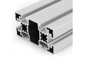 PG45 90×45 mm Six Slot Aluminium Strut Profile Rectangular Machine Beam
A 90 x 45 mm six slot PG45 aluminium strut profile for machine frames…
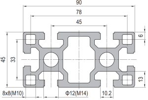 PG45 90 x 45 mm Six Slot Aluminium Strut Profile Heavy Rectangular Beam
90 x 45 mm six-slot heavy aluminium strut profile with 10.2 mm grooves and…
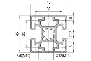 PG45 45 x 45 mm Two Slot Type B Aluminium Strut Profile Opposite Rail
45 x 45 mm two-slot Type B aluminium strut profile with slots on opposite…
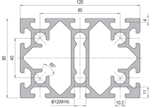 PG40 120 x 80 mm Ten Slot Aluminium Strut Profile Wide Heavy Beam
120 x 80 mm ten-slot aluminium strut profile with six slots on the two…
 PG40 80×40 mm Six Slot Aluminium Strut Profile Standard Wall Beam
An 80 x 40 mm six slot standard wall PG40 aluminium strut profile. Two…
