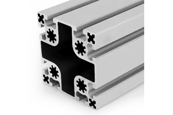
PG50 100×100 mm Eight Slot Aluminium Strut Profile for Heavy Machine Columns
A 100 x 100 mm eight slot PG50 aluminium strut profile with two slots per face on a 50 mm pitch, 6.8 x 6.8 mm M8 corner holes on an 85 mm square and a Ø12 mm M14 centre bore.
| Material | Aluminium |
|---|---|
| Alloy Grade | 6063-T5 |
| Temper | T5 |
| Section Size | 100 x 100 mm |
| Slot | 8 x 10.2 mm groove, 8 mm mouth, 50 mm pitch, two slots per face |
| Length | 6 m stock, cut to drawing to +/-0.5 mm |
| Tolerance | EN 755-9 / GB/T 6892, wall +/-0.15 mm |
| Surface | Mill finish / clear anodised / black anodised |
| MOQ | 150 |
| Lead Time | 22-32 days after deposit for mill finish |
| Loading Port | Shanghai / Ningbo |
| Supply Ability | 200 t per month |
| Payment Terms | T/T 30% deposit + 70% before shipment | L/C at sight |
| Trade Terms | FOB | CIF | EXW |
| Certifications | ISO 9001:2015 | EN 755-9 | RoHS | REACH |
Structural framing · PG50 column section
A PG50 100 x 100 mm eight slot aluminium strut profile is a square column on a 50 mm slot pitch with a 10.2 mm groove and an 8 mm slot mouth. There are two slots on each face, 50 mm apart, four 6.8 x 6.8 mm corner holes tapped M8 sitting on an 85 mm square, and a Ø12 mm centre bore tapped M14. The flange is 6 mm and the web 13 mm, and the section weighs about 9.2 kg/m. It is supplied in 6063-T5, cut and machined to order.
The thing to notice is that this section carries two fixing sizes, and they are not interchangeable. The M8 corner holes take the cross connections and the brackets; the M14 centre bore takes the structural end connection, with about three times the bolt area. Reading them as one system rather than two is where most frames go wrong.
Two fixing sizes, two jobs
The section has eight slots, four corner holes and one centre bore, and the three are sized for different things. Mixing them up is the usual reason a 100 mm column ends up with connections that are either oversized or the weak point of the frame.
| Fixing | Size | Bolt area | What it is for |
|---|---|---|---|
| T-slot | 10.2 mm groove, 8 mm mouth | M8 slot nut | Anything that has to slide or be adjusted: brackets, rails, panels, clamps |
| Corner holes | 6.8 x 6.8 mm, tapped M8 | 36.6 mm2 | Cross connections, end plates and corner joints, on an 85 mm square |
| Centre bore | Ø12 mm, tapped M14 | 115 mm2 | The structural end connection: base plates, butt joints, splice plates |
The M14 bolt has a tensile stress area of about 115 mm2 against about 36.6 mm2 for the M8. That is a factor of three, and it is the reason the centre bore exists at all: the end of a column is where a frame concentrates its load, and it is the one place where the bolt size should not be trimmed.
The four corner holes sit on an 85 mm square. That is the base plate and end plate pattern: 85 x 85 mm, four M8 fixings. If a matching plate already exists in the design, this is the dimension that has to agree with it.
What the 50 mm pitch changes
The slot itself is the same size as the 40 series: a 10.2 mm groove with an 8 mm mouth, taking M8 nuts. What changes with the 50 series is the pitch and the amount of aluminium between the slots.
| 40 series on a 100 mm face | 50 series on a 100 mm face | |
|---|---|---|
| Slot pitch | 40 mm | 50 mm |
| Slot centres on the face | 40 mm apart | 50 mm apart |
| Slots per face | Two | Two |
| Web between slots | Narrower | Wider |
| Corner hole | 5 x 5 mm, tapped M6 | 6.8 x 6.8 mm, tapped M8 |
| Corner hole bolt area | 20.1 mm2 | 36.6 mm2 |
| Centre bore | Ø12 mm, tapped M14 | Ø12 mm, tapped M14 |
Two things are worth taking from that table. The first is that the corner holes grow while the slots do not: the 50 series keeps the same M8 slot but moves the corner fixing from M6 to M8, about 82 per cent more bolt area. The second is that the wider pitch puts more metal between the slots, which is where the bending load in a column actually goes.
The counter-intuitive part
Put the 45 series 90 x 90 mm column next to this one and something unexpected appears: the smaller section has the bigger corner bolt.
| 45 series 90 x 90 mm | 50 series 100 x 100 mm | |
|---|---|---|
| Envelope | 90 x 90 mm | 100 x 100 mm |
| Slot pitch | 45 mm | 50 mm |
| Slot mouth | 10 mm | 8 mm |
| Corner hole | 8 x 8 mm, tapped M10 | 6.8 x 6.8 mm, tapped M8 |
| Corner hole bolt area | 58.0 mm2 | 36.6 mm2 |
| Centre bore | Ø12 mm, tapped M14 | Ø12 mm, tapped M14 |
| Wall | 6 mm flange / 13 mm web | 6 mm flange / 13 mm web |
| Weight | approx. 7.60 kg/m | approx. 9.20 kg/m |
| Second moment of area | approx. 230 cm4 | approx. 380 cm4 |
The 50 series is not the 45 series with bigger bolts. It is a bigger envelope with smaller corner bolts, and it buys stiffness rather than joint capacity: about 65 per cent more second moment of area for about 21 per cent more weight.
That turns the choice into a question about which part of the frame is failing. If the members are too flexible, go up a section size and accept the M8 corner holes — they are not the problem. If the members are stiff enough but the connections keep slipping, coming loose or needing to be very numerous, the M10 corner holes of the 45 series are the direct answer and a bigger section will not help.
Specifying a 100 mm column
- Check what is actually failing Deflection or sway points at the section; loosening or slipping joints points at the bolt. Decide this before choosing between the 45 and 50 series.
- Put the structural connection on the centre bore The M14 bore is the strongest fixing in the section. Use it for the base plate or the butt joint, and keep the corner holes for cross members.
- Use the 85 mm square for plates The four M8 corner holes sit on an 85 mm square. Any base plate or end plate drawn for this section has to match that pattern.
- Expect M8 nuts in the slots The slot mouth is 8 mm and the groove is 10.2 mm, so 40 series M8 slot nuts fit. There is no separate 50 series nut to order.
- Remember the pitch is 50 mm Two slots per face, 50 mm apart. A bracket drilled for a 40 or 45 mm pitch will not line up.
- Plan the lift At about 9.2 kg/m a 6 m length is a two-person lift and needs support along its length in storage to stop it taking a set.
Frequently asked questions
What is the difference between the M8 corner holes and the M14 centre bore?
They are two different fixings with different jobs. The corner holes are tapped M8 with about 36.6 mm2 of bolt area and take cross connections and brackets. The centre bore is tapped M14 with about 115 mm2 and takes the structural end connection.
Why does the 50 series have smaller corner bolts than the 45 series?
Because the 50 series buys stiffness, not joint capacity. The 100 x 100 mm section is about 65 per cent stiffer than a 90 x 90 mm 45 series section, but its corner holes are M8 against the 45 series M10.
Which series should I use, 45 or 50?
If the frame is too flexible, use the 50 series for the bigger section. If the frame is stiff enough but the joints slip or loosen, use the 45 series for its M10 corner holes.
Does it take 40 series slot nuts?
Yes. The slot groove is 10.2 mm and the mouth is 8 mm, the same as the 40 series, so standard M8 slot nuts fit.
What is the corner hole pattern?
The four corner holes are 6.8 x 6.8 mm, tapped M8, on an 85 mm square.
Do you machine the base plates?
Yes. We cut to length, face and square the ends, tap the corner holes and the centre bore, and machine base and end plates to the 85 mm pattern. Send DWG, DXF, STEP or PDF.
Send the column load and the plate pattern
Tell us whether the frame is failing on deflection or on the connections, and send the base plate pattern if one exists. We will confirm the section and quote cut lengths with the corner holes and the M14 centre bore machined to your drawing.
Request a QuoteRelated Products
 PG50 100×50 mm Six Slot Aluminium Strut Profile Rectangular Machine Beam
A 100 x 50 mm six slot PG50 aluminium strut profile with slots on…
 PG45 90×45 mm Six Slot Aluminium Strut Profile Rectangular Machine Beam
A 90 x 45 mm six slot PG45 aluminium strut profile for machine frames…
 PG45 90 x 45 mm Six Slot Aluminium Strut Profile Heavy Rectangular Beam
90 x 45 mm six-slot heavy aluminium strut profile with 10.2 mm grooves and…
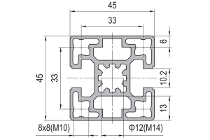 PG45 45 x 45 mm Two Slot Type B Aluminium Strut Profile Opposite Rail
45 x 45 mm two-slot Type B aluminium strut profile with slots on opposite…
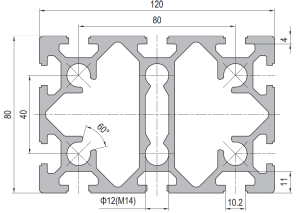 PG40 120 x 80 mm Ten Slot Aluminium Strut Profile Wide Heavy Beam
120 x 80 mm ten-slot aluminium strut profile with six slots on the two…
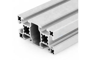 PG40 80×40 mm Six Slot Aluminium Strut Profile Standard Wall Beam
An 80 x 40 mm six slot standard wall PG40 aluminium strut profile. Two…
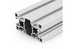 PG40 80×40 mm Six Slot Light Aluminium Strut Profile for Panel Frames
An 80 x 40 mm six slot light wall PG40 aluminium strut profile for…
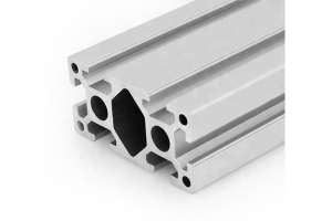 PG40 80 x 40 mm Six Slot Aluminium Strut Profile Heavy Rectangular Beam
80 x 40 mm heavy-wall six-slot aluminium strut profile with four slots on the…
