Standard sizes · series matrix
Aluminium Profile Standard Sizes: How the Series Matrix Actually Works
A 4040 is not one product. The 30 series and the 40 series share the same slot on most European grids. And “standard size” is not a specification. Here is the full T-slot series matrix — slot mouth, channel, centre bore, slot pitch, second moment of area — and the seven lines a purchase order has to carry before a supplier can quote the right thing.
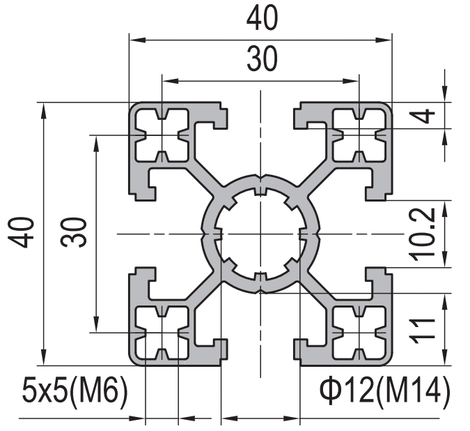
Quick answer
- The number is the envelope in millimetres. 4040 is 40 × 40 mm, 4590 is 45 × 90 mm, 30120 is 30 × 120 mm. The first pair of digits is one side, the second pair is the other.
- The series number and the envelope are two different things. A 40 series covers 40 × 40, 40 × 60 and 40 × 80 — all three share the same slot geometry and the same hardware, but they are not interchangeable structurally.
- The slot mouth decides the fixing class, not the envelope. A 6 mm mouth takes M5 class nuts, an 8 mm mouth takes M6 and M8, a 10.2 mm mouth takes M8 and M10. Two profiles with the same outside size can have different mouths.
- One envelope, three different members. A 40 × 40 light, standard and heavy wall look identical from the outside and differ by a factor of two in stiffness (about 6.1 to about 12.4 cm4) and by 80 per cent in weight (1.30 to 2.35 kg/m).
- “Standard size” is not a specification. A usable purchase order needs seven lines: envelope, series, wall, alloy, temper, tolerance class and cut length.
- Tolerance follows the circumscribing circle, not the reputation of the supplier. Under EN 755-9 a 20 × 20 sits in a tighter bucket than an 80 × 80, and the standard tells you the exact figure.
Also searched as aluminium profile standard sizes, 40x40 aluminium extrusion dimensions, T-slot profile size chart, aluminium profile series chart, standard aluminium extrusion sizes mm, aluminium profile catalogue dimensions.
What the number in the name actually tells you
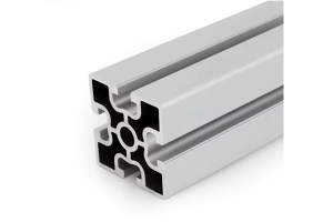
The naming convention is the easiest thing to get right and the most commonly misread. Take 4590. It is not a model number, a strength class or a load rating. It is a cross-section measurement: 45 mm on one side, 90 mm on the other. The same rule gives you 2020, 2040, 3030, 4040, 4545, 6060, 8080 and the deep beam sections such as 30120 and 50100.
Two consequences follow immediately, and both catch buyers out.
First, the name is silent about the wall. The overwhelming majority of aluminium T-slot extrusions are sold under a name that describes only the outer envelope. A 40 × 40 heavy wall and a 40 × 40 light wall are both sold as “4040”. They take the same brackets, the same end caps and the same slot nuts, they look the same in a photograph, and they behave differently by a factor of two under load. If your drawing says 4040 and nothing else, the supplier will ship whatever wall their stock happens to be.
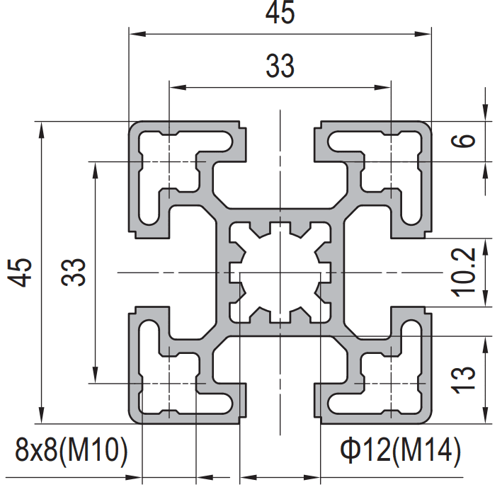
Second, the name is silent about the slot. The slot mouth is the opening at the face of the profile, and it is the feature every accessory engages with. It is set by the series, not by the envelope, and the series is not always what the name suggests. A 40 series profile has an 8 mm mouth on most European grids; a 45 series has a 10 mm mouth. Nothing crosses over — a 40 series T-nut will not seat in a 45 series slot, and the outer dimensions being 5 mm apart makes that mistake easy to make and expensive to discover.
The trap in one line
If a quotation comes back for “4040” without a wall thickness, a slot class and a tolerance class, you have been quoted a category, not a product. Ask for the section drawing and the wall before you compare prices.
The series matrix
Below is the matrix we work to. Every figure is a nominal value for a standard-wall section of that series in 6063-T5, and the inertia column is the second moment of area about the strong axis, which is the number that governs deflection. Treat the inertia and weight figures as typical values for the series rather than as a promise for any single item — wall thickness moves them, which is the subject of the next section.
| Series | Typical envelopes | Slot mouth | Fixing class | Centre bore | Slot pitch | I (cm4) | Weight (kg/m) |
|---|---|---|---|---|---|---|---|
| 20 series | 20 × 20, 20 × 40, 20 × 60 | 6.0 mm | M4, M5 | ⌀4.2 mm | 20 mm | 0.6 – 2.0 | 0.55 – 1.15 |
| 30 series | 30 × 30, 30 × 60 | 6.0 – 8.0 mm | M5, M6 | ⌀6.8 mm | 22 – 24 mm | 2.6 – 3.6 | 0.95 – 1.30 |
| 40 series | 40 × 40, 40 × 60, 40 × 80 | 8.0 mm | M6, M8 | ⌀6.8 – 8.2 mm | 30 mm | 6.1 – 12.4 | 1.30 – 2.35 |
| 45 series | 45 × 45, 45 × 60, 45 × 90 | 10.0 mm | M8, M10 | ⌀12 mm | 33 mm | 10.5 – 19.5 | 1.90 – 3.15 |
| 50 series | 50 × 50, 50 × 100 | 10.2 mm | M8, M10 | ⌀12 mm | 40 mm | 25 – 42 | 3.10 – 3.60 |
| 60 series | 60 × 60, 60 × 90 | 10.2 mm | M8, M10 | ⌀12 mm | 48 mm | 25 – 38 | 2.60 – 6.40 |
| Deep beam | 30 × 120, 50 × 100, 80 × 200 | 10.2 mm | M8, M10, M12 | ⌀12 – 16 mm | varies | 50 – 150 | 3.60 – 19.5 |
Read the table across the middle and the structure of the market becomes clear. Between the 30 series and the 45 series the inertia goes up by a factor of roughly five while the weight only goes up by a factor of two and a half. That gap is where most of the interesting design decisions live, and it is why “just go one size up” is often better value than “order the heavy wall”.
Relative bending stiffness
Second moment of area, standard wall, strongest axis. Bar length is proportional to the figure in the matrix above.
Read it as a step function, not a ramp. The jump from the 30 series to the 40 series is worth 2.6 times; the jump from the 45 series to the 50 series is worth only 1.6 times. Two of the steps carry most of the gain, and picking the wrong one is how a frame ends up heavy and still flexible.
The deep beam rows deserve a note. A 30 × 120 is not a big frame member; it is a shallow beam, and its 115 cm4 about the strong axis comes from depth rather than from material. It is the right answer when a worktop or a conveyor rail has to span 2 m without sagging, and the wrong answer when the load arrives from the side, where its weak-axis inertia is closer to 12 cm4.
One envelope, three different members
This is the part of the matrix that costs people the most money, because the difference is invisible. Three sections below are all sold as 40 × 40 four-slot. They have the same outside dimensions to the millimetre, the same slot pitch and the same slot class. Only the wall changes.
| Property | 40 × 40 light | 40 × 40 standard | 40 × 40 heavy |
|---|---|---|---|
| Wall thickness | about 1.5 mm | about 2.0 mm | about 2.6 mm |
| Weight | 1.30 kg/m | 1.75 kg/m | 2.35 kg/m |
| Second moment of area | 6.1 cm4 | 9.2 cm4 | 12.4 cm4 |
| Stiffness per kg/m | 4.7 | 5.3 | 5.3 |
| Centre bore | ⌀6.8 mm, taps M8 | ⌀8.2 mm, taps M14 | ⌀8.2 mm, taps M14 |
| Allowable point load at 1,000 mm span | about 70 kg | about 105 kg | about 142 kg |
Two things in that table are worth pausing on.
The stiffness gain is real but sub-linear. Going from light to heavy wall adds 81 per cent more aluminium (1.30 to 2.35 kg/m) and buys 103 per cent more inertia. In a purely stiffness-driven design that is a good trade. But it is a worse trade than it looks, because the same material spent on a larger envelope buys far more. Moving from a 40 × 40 standard to a 45 × 45 standard adds 46 per cent more weight and buys 68 per cent more inertia — and it also brings a larger slot class, a bigger centre bore and a stiffer joint. Wall thickness is the upgrade you take when the envelope is fixed by an existing frame or a panel cut-out. It is not the upgrade you take by default.
The bore is a hidden specification. Look at the centre bore column. The light-wall 40 × 40 has a 6.8 mm bore that taps M8; the standard and heavy have an 8.2 mm bore that taps M14. If your design puts a levelling foot or a castor into the end of the profile, the wall grade decides which thread you can have — and the light wall cannot be upgraded by asking the machine shop nicely, because there is not enough metal around the bore.
What this costs when it goes wrong
A frame specified as “4040”, built from light wall, and then loaded to a calculation done for standard wall will deflect about 50 per cent more than predicted. Nothing will break. The machine will simply not hold position, and the cause will be invisible because every member is stamped 4040.
Where “standard” stops, and the seven lines a PO needs
Suppliers publish catalogues of standard sections, and the word “standard” in that context means one thing only: the die already exists, so there is no tooling charge. It does not mean the section is standardised across the industry, and it does not mean two suppliers’ 4040 will interchange.
The practical fix is to stop treating the name as a specification and to write the specification out. Seven lines are enough for a supplier to quote unambiguously and for you to reject a delivery that does not match.
- Envelope. 40 × 40 mm nominal, plus the drawing. The drawing is what settles corner radius, slot shape and bore position, and it is the only defence against a supplier whose “4040” is a different die.
- Series and slot class. State the slot mouth, not just the series: “8.0 mm mouth, M6/M8 class”. This is the line that prevents the cross-series hardware mistake.
- Wall thickness, with a tolerance. Nominal wall plus the tolerance you will accept. “2.0 mm nominal, EN 755-9 group I” is a specification; “standard wall” is a hope.
- Alloy and temper. 6063-T5 for general framing. Write it out even when you expect it, because a substitution to a softer temper is undetectable at goods-in without a tensile test.
- Tolerance class. EN 755-9 for general engineering, or the tighter class your assembly actually needs. Do not leave it blank and do not ask for the tightest class “just to be safe” — you will pay for capability you cannot use.
- Cut length and end condition. Length, length tolerance, squareness of cut ends, and whether the ends are deburred or tapped.
- Inspection evidence. Which certificate you want — mill certificate for the material, dimensional report for the cut length, or both — and which dimensions are critical to function.
Line three and line five are the ones that get left out, and they are the two that decide whether the profiles you receive will assemble. The next two sections give you the numbers to put on them.
Tolerance follows the circumscribing circle, not the side length
Almost every buyer who looks at an extrusion tolerance table expects it to be indexed by the profile size. It is not. EN 755-9 indexes the cross-sectional tolerance by two things: the dimension being toleranced, and the diameter of the smallest circle that will contain the whole cross-section — the circumscribing circle, usually written CD.
That second index is the one people miss. For a square section the circumscribing circle is the diagonal, not the side. A 40 × 40 has a 40 mm side but a 56.6 mm circumscribing circle. A 60 × 60 has an 84.9 mm circle. A 90 × 90 crosses the 100 mm boundary and lands in the next tolerance bucket, even though no single dimension on the section is anywhere near 100 mm.
Here are the actual figures for alloy group I, which is where 6063, 6060, 6005 and 6063A sit. Group II — 6061 and 6082 — gets roughly 40 to 60 per cent more tolerance for the same geometry, which is a useful reminder that the alloy you specify changes what you can hold.
| Dimension H | CD ≤ 100 mm | 100 < CD ≤ 200 | 200 < CD ≤ 300 |
|---|---|---|---|
| up to 10 mm | ±0.25 | ±0.30 | ±0.35 |
| 10 to 25 mm | ±0.30 | ±0.40 | ±0.50 |
| 25 to 50 mm | ±0.50 | ±0.60 | ±0.80 |
| 50 to 100 mm | ±0.70 | ±0.90 | ±1.10 |
| 100 to 150 mm | – | ±1.10 | ±1.30 |
Apply that to the sections in the matrix and you get the tolerance you should actually expect on the width, without asking anyone.
| Section | Dimension H | Circumscribing circle | EN 755-9 tolerance, group I |
|---|---|---|---|
| 20 × 20 | 20 mm | 28.3 mm | ±0.30 mm |
| 30 × 30 | 30 mm | 42.4 mm | ±0.50 mm |
| 40 × 40 | 40 mm | 56.6 mm | ±0.50 mm |
| 45 × 45 | 45 mm | 63.6 mm | ±0.50 mm |
| 60 × 60 | 60 mm | 84.9 mm | ±0.70 mm |
| 80 × 80 | 80 mm | 113 mm | ±0.90 mm |
| 90 × 90 | 90 mm | 127 mm | ±0.90 mm |
| 100 × 100 | 100 mm | 141 mm | ±0.90 mm |
Two practical readings come out of that table. The first is that a 30, 40 and 45 series section all carry the same ±0.50 mm on their main dimension — the envelope size barely changes the tolerance until the profile gets genuinely large. The second is that a supplier quoting “±0.1 mm on the profile” is not quoting an extrusion tolerance at all; they are quoting a machining tolerance, and if they mean it they are going to cut or mill the section to get there.
How to use this at quotation stage
If your drawing needs a profile dimension tighter than the table gives, do not push the extruder. Change the drawing so the tight feature is a machined feature — a milled face, a reamed bore, a tapped hole. Extrusion tolerance and machining tolerance are separate budgets, and mixing them is how projects end up paying twice.
Choosing by span, not by size
The single most useful thing you can do with the matrix is to stop asking “what size do I need” and start asking “what span do I have to cross”. For a machine frame the governing criterion is almost never material failure; it is how far the member bends. A simply supported member with a load at mid-span is limited by:
Allowable centre point load at L/300
F [kg] = 1.1417 × 10⁷ × I [cm4] ÷ L [mm]2Simply supported, single point load at mid-span, E = 70,000 N/mm2, deflection limited to span/300. The constant already carries the unit conversions, so you can read inertia straight off the matrix table.
Run that across the series and you get a table you can use directly in a design review. The figures below are kilograms at mid-span.
| Member | I (cm4) | 500 mm | 1,000 mm | 1,500 mm | 2,000 mm | 3,000 mm |
|---|---|---|---|---|---|---|
| 30 × 30 light | 2.6 | 119 | 30 | 13 | 7 | 3 |
| 30 × 30 standard | 3.6 | 164 | 41 | 18 | 10 | 5 |
| 40 × 40 light | 6.1 | 279 | 70 | 31 | 17 | 8 |
| 40 × 40 standard | 9.2 | 420 | 105 | 47 | 26 | 12 |
| 40 × 40 heavy | 12.4 | 566 | 142 | 63 | 35 | 16 |
| 45 × 45 standard | 15.5 | 708 | 177 | 79 | 44 | 20 |
| 45 × 45 heavy | 19.5 | 891 | 223 | 99 | 56 | 25 |
| 60 × 60 standard | 26 | 1,187 | 297 | 132 | 74 | 33 |
The shape of that table is the whole lesson. Doubling the span costs you a factor of four in allowable load, because deflection goes with the cube of span. Going from a 40 × 40 light to a 40 × 40 heavy, at the same span, buys you roughly a factor of two. Going from a 40 × 40 light to a 45 × 45 heavy buys you about 2.2 — for less than twice the weight.
Which is why the useful first question in a frame design is not “40 or 45” but “can I add a support at the middle”. Halving an unsupported span multiplies the allowable load by four and costs one extra member and two brackets. No section change comes close to that return.
Frequently asked questions
What do the numbers in 2020, 3030 and 4040 mean?
Do the 30 series and the 40 series use the same slot?
Is a bigger profile always stronger?
Why does a 90 × 90 profile have a different tolerance from a 60 × 60?
Can I use the same brackets on a 40 × 40 and a 45 × 45?
How many lines does a purchase order need to fully specify a profile?
Tell us the envelope, the wall and the span
We extrude and machine the 20 through 60 series and the deep beam sections in 6063-T5, in light, standard and heavy wall, cut to length, end-tapped, drilled or supplied as an assembled kit. Send the drawing and the span and we will come back with the section and the wall that actually holds it — not the one that happens to be in stock.
Related reading
Twelve more engineering notes from this blog, picked for this article — plus every category below.
 Engineering Design4040 T-Slot Aluminium Profile for Machine Frames: Choose It by Deflection
 ApplicationsAluminium Partitions: The Three Performance Numbers Behind the Aesthetic
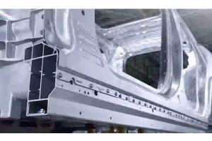 Engineering DesignHow to Choose an Aluminium Extrusion Profile: The Three Decisions That Bind
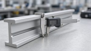 Engineering DesignWhat EN 755-9 Allows: Aluminium Extrusion Tolerances
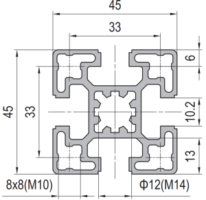 Engineering DesignHow to Choose the Right T-Slot Aluminium Profile Size
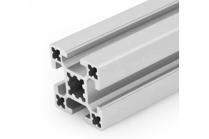 Engineering DesignWhat Is a 4040 Aluminium Profile? (Weight, Slot and Load)
 Materials and EngineeringIndustrial Aluminium Extrusion: Five Advantages and the Conditions Attached to Each
 Engineering DesignCustom Aluminium Extrusion: From Drawing to Production
 ApplicationsESD-Safe Aluminum Profile Workbenches: Why Anodising Alone Fails the Audit
 ApplicationsAluminium Profile Fish Tank Frames: Glass Load, Salt Water, and the Alloy Question
 Sourcing and ProcurementAuditing an Aluminium Profile Supplier: Factory, Trader, or Something in Between
 ApplicationsDesigning Machine Guards and Safety Fences in Aluminium Profile: An ISO 14120 Guide
