Profile selection · decision order
How to Choose an Aluminium Extrusion Profile: The Three Decisions That Bind
Most selection guides are nine steps in the wrong order. Nine questions look like nine decisions, and they are not: span, load position and deflection budget are the only inputs, and the section, the slot, the alloy, the finish and the accessory family are all consequences. Here is the order that stops you from committing to the expensive choices before you know the answers.
Quick answer
- Only three things are inputs: the unsupported span, the load and where it sits on the span, and the deflection you are willing to accept. Everything else in a selection guide is an output or a commitment.
- The deflection budget moves the answer more than the section does. On a 1,000 mm span, a 40 × 40 standard carries 105 kg at a L/300 limit and 63 kg at L/500. Same profile, same load, 67 per cent difference — from a number most buyers never write down.
- Three decisions are irreversible: the slot standard, the cut length and end machining, and the finish sequence. Get those three right and the rest of the project can be corrected as you go.
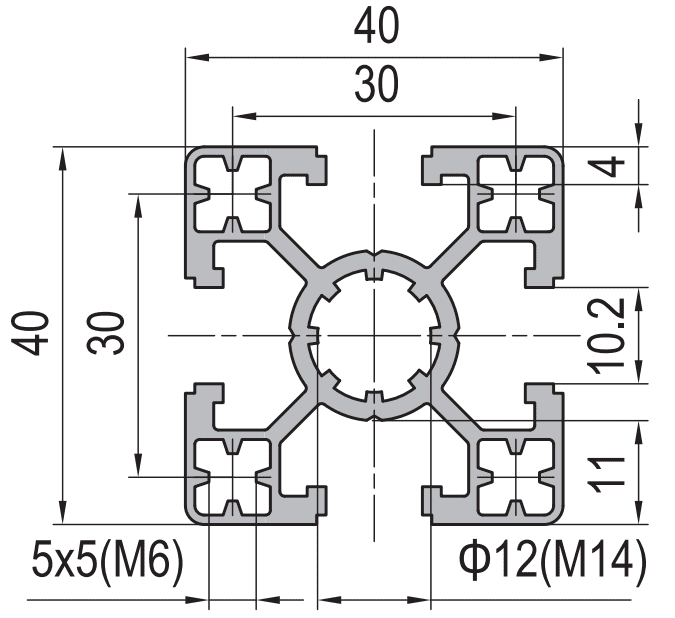
- The slot standard locks the accessory catalogue, not just the nut. A 30 series and a 40 series both use an 8 mm mouth, but their slot pitches are 22–24 mm and 30 mm. The nut crosses over; the bracket does not reach.
- 6061-T6 does not reduce deflection. It raises yield from 110 to 240 MPa — and moves the modulus by about one per cent. Deflection-governed frames gain nothing from the upgrade.
- Write the deflection budget on the drawing. A profile quotation that comes back without a span and a limit is a price, not an answer.
Also searched as how to choose aluminium extrusion profile, aluminium profile selection guide, choosing aluminium profile size, t-slot profile selection, aluminium extrusion specification, 40x40 profile selection.
Nine questions, three decisions
The standard selection guide asks nine things: required size, slot size, alloy, application match, length, surface finish, accessory compatibility, supplier, and a final checklist. It is a complete list. What it is not is a sequence, because the nine items are not the same kind of thing. Three of them are inputs you have to measure or decide. Four are outputs that follow from those inputs. Two are commitments you make once and then live with.
Sort them that way and the guide turns into a procedure.
| Question | What it actually is | Cost of getting it wrong |
|---|---|---|
| Required profile size | Output | Recalculable before the order, expensive after |
| T-slot size | Commitment | Every nut, bolt, bracket and hinge in the project |
| Aluminium alloy | Input with narrow effect | Small — it changes strength, not stiffness |
| Match to application | Output | A framing decision, not a purchase decision |
| Profile length | Commitment | Scrap, per piece, immediately |
| Surface finish | Commitment | Lead time, and whether the frame can be bonded |
| Accessory compatibility | Consequence of the slot | Follows automatically from the slot standard |
| Manufacturer | Commercial | Delivery and documentation, not the drawing |
| Final checklist | The output of the first eight | Nothing, if the first eight were done in order |
The practical value of this sort is that it tells you what to do first. Measure the span. Write down the load and where it acts. Decide the deflection limit. Then let the section fall out of the arithmetic, and only then make the three commitments. Most over-specified frames in the field are not the result of a bad calculation; they are the result of a slot standard and a cut list being fixed before the span was ever measured.
Input one and two: the span, and where the load sits
The span is the distance between supports, not the length of the profile. That distinction alone accounts for a large share of frames that deflect more than expected: a 3,000 mm rail with three intermediate supports has a 750 mm span, and it is eight times stiffer in deflection terms than the same rail supported only at its ends, because deflection goes with the cube of span.
The second input is the position of the load, and it is the one that is almost never written down. The same force produces a very different deflection depending on where it acts, and the coefficient that describes it is a small number you can carry in your head.
| Load case | Coefficient k | Deflection | Where you meet it |
|---|---|---|---|
| Point load at mid-span, simply supported | 1.00 | δ = F L³ / (48 E I) | The default case in every catalogue |
| Two equal point loads at the quarter points | 0.5625 | δ = 9 F L³ / (768 E I) | A machine on two feet, symmetric |
| Uniformly distributed load | 0.625 | δ = 5 w L⁴ / (384 E I) | Panels, cable, guarding, a conveyor bed |
| Point load at the eighth point | 0.19 | δ = 0.19 F L³ / (48 E I) | A sensor or a bracket near a support |
| Cantilever, load at the free end | 16.0 | δ = F L³ / (3 E I) | An overhanging light arm or a guard door |
Read the first and last rows together and the design lesson is obvious. Moving the same load from the middle of a supported span to the end of an overhang multiplies the deflection by sixteen. Nothing about the profile changed. This is why a cantilevered operator panel or a cantilevered light arm needs a section two sizes bigger than the rail it hangs from, and why “it is only a light arm” is a sentence that precedes most sagging frames.
Input three: the deflection budget
The third input is the only one that is a business decision rather than a measurement: how much movement is acceptable. There is no universal answer, but there are three conventions that cover most industrial work, and choosing between them is worth more money than any material substitution.
L/300
About 3.3 mm on a 1,000 mm span. The default for machine frames, guarding, conveyors and structures where nothing is being measured. Roughly a third of the yield capacity of a typical 40 series section, so deflection binds well before the material does.
L/500
About 2 mm on 1,000 mm. Used where a sensor, a probe, a camera or a laser is mounted on the structure, because deflection becomes a measurement error. Costs 67 per cent of the allowable load against L/300.
1 mm absolute
Not a ratio. Where an inspection camera has a depth of field of a few millimetres, the budget is the depth of field, not a fraction of the span. This is where deflection stops being a comfort question and starts being a specification.
The only two equations you need
δ = k · F · L³ / (E · I)I_required = k · F · L³ / (E · δ_allow)E = 70,000 N/mm² for 6xxx aluminium. F in newtons, L in millimetres, I in mm⁴. Divide the result by 10,000 to compare it against a catalogue figure quoted in cm⁴.
A worked example, and the answer that costs nothing
A drive unit weighing 80 kg is mounted at the middle of a 1,800 mm rail. The customer has asked for L/500 because a sensor is mounted on the same member.
- Convert the load. 80 kg × 9.81 = 785 N. The coefficient k is 1.0 for a central point load.
- Set the allowance. 1,800 / 500 = 3.6 mm.
- Solve for I. I = 1.0 × 785 × 1,800³ / (70,000 × 48 × 3.6) = 785 × 5.832 × 10⁹ / 1.2096 × 10⁷ = 378,500 mm⁴, or about 38 cm⁴.
- Read the catalogue. A 45 × 45 heavy gives about 19.5 cm⁴ and fails by a factor of two. A 60 × 60 heavy gives about 38 cm⁴ and just passes, at 6.4 kg/m.
- Try the cheap alternative. Put a support at the middle, so the unsupported span becomes 900 mm. Deflection scales with L³, so the required inertia falls by a factor of eight, to about 4.7 cm⁴. A 40 × 40 standard at 9.2 cm⁴ covers it with margin.
What that comparison is worth
Option one is 1.8 m of 60 × 60 heavy at 6.4 kg/m: about 11.5 kg of profile. Option two is 1.8 m of 40 × 40 standard at 1.75 kg/m plus a 900 mm post and two brackets: about 3.2 kg plus a post. The cheap option is roughly a third of the material, half the cost, and easier to handle during assembly. It also has to be decided at the drawing stage, because a mid-span support cannot be added to a finished frame without taking it apart.
Which is why the useful first question in profile selection is not “40 or 45”. It is “where can I put a support”. Section changes move the answer by tens of per cent. Support positions move it by multiples.
The three commitments, in the order they become expensive
Once the arithmetic is done, three decisions remain that cannot be undone cheaply. They are worth thinking about as a group, because the order in which they are usually taken is the opposite of the order in which they should be taken.
| Commitment | What it locks | Cost to reverse | When to make it |
|---|---|---|---|
| Slot standard and mouth | The entire accessory catalogue: nuts, bolts, brackets, hinges, feet, handles, panel strips | Every accessory already bought, plus the design of every joint | After the span is known, before any hardware is ordered |
| Cut length and end machining | The physical parts. A 1,750 mm member cannot become a 1,800 mm one | Scrap value of the piece, plus the lead time for a replacement | After the frame layout is fixed, before the material is cut |
| Surface finish and sequence | Lead time, appearance, and whether the frame can be electrically bonded | A second finishing pass, or a masking operation that should have been free at extrusion | Before extrusion, because masking is cheap then and expensive later |
Everything else can be corrected as the project develops. The wall thickness can be upgraded on the next order. The accessory brand can change freely within the same slot standard. The section can be revised for the second machine. It is only these three that carry a real penalty, and only the slot standard is genuinely permanent — which is why the slot deserves the most thought and usually gets the least.
The slot standard is not the same thing as the envelope
Buyers routinely assume that the series number and the slot are the same decision. They are not, and the mismatch produces one of the most irritating failures in modular framing: a nut that fits a slot it was not designed for, in a joint that will not close.
| Series | Slot mouth | Slot pitch | Fixing class | What crosses over |
|---|---|---|---|---|
| 20 series | 6.0 mm | 20 mm | M4, M5 | Nothing crosses to or from the 30 series |
| 30 series | 6.0 – 8.0 mm | 22 – 24 mm | M5, M6 | An 8 mm M8 T-nut drops into an 8 mm 30 series slot, but a 40 series bracket does not span the 22–24 mm pitch |
| 40 series | 8.0 mm | 30 mm | M6, M8 | The industry default; the widest accessory availability |
| 45 series | 10.0 mm | 33 mm | M8, M10 | Nothing crosses from 40 series; 3 mm of mouth and 3 mm of pitch |
| 50 and 60 series | 10.2 mm | 40 and 48 mm | M8, M10 | The M10 T-nut is shared; the brackets are not |
The expensive misunderstanding
Because 30 series and 40 series share an 8 mm mouth on most European grids, the nut is genuinely interchangeable. That fact gets extended, incorrectly, to the whole system. The bracket, the hinge, the foot and the panel strip are all dimensioned around the slot pitch, which is 22 to 24 mm on the 30 series and 30 mm on the 40 series. Buying “the same 8 mm hardware” for both is how a project ends up with two boxes of unusable brackets.
Alloy and temper: what the upgrade actually buys
Alloy choice is presented in most guides as a strength decision, and it is — but strength is rarely the limit in a profile frame. The distinction matters because the two properties respond very differently to the change.
| Property | 6063-T5 | 6061-T6 | Change |
|---|---|---|---|
| Proof stress Rp0.2, EN 755-2 | 110 MPa (3–25 mm) | 240 MPa | 2.2 × |
| Tensile strength Rm, EN 755-2 | 160 MPa (3–25 mm) | 260 MPa | 1.6 × |
| Young’s modulus E | about 69.5 GPa | about 68.9 GPa | about 1 % lower |
| Density | 2.70 g/cm³ | 2.70 g/cm³ | unchanged |
| Extrudability and surface finish | Excellent | Harder to extrude, more die wear | Cost and lead time |
Read the first and third rows together. Moving from 6063-T5 to 6061-T6 more than doubles the stress at which the material yields, and changes the stiffness by about one per cent in the wrong direction. A frame whose limit is deflection — which is nearly every frame — gains nothing at all from the upgrade, and pays for it in extrusion difficulty, tool wear and price.
Where the upgrade does pay is where the failure mode is strength rather than movement: a heavily loaded joint, a member in tension, a tapped end taking a bolt load, a bracket that has to resist a peak shock rather than a working load. And there is a documentation point that catches exporters out. The same designation does not mean the same number on both sides of the Atlantic: under EN 755-2 a 6063-T5 section at 3 to 25 mm wall is specified at 160 / 110 MPa, while ASTM B221-02 puts the same designation at 152 / 110 MPa up to 12.7 mm and 145 / 103 MPa from 12.7 to 25.4 mm. That is roughly 15 per cent on tensile and 18 per cent on yield, for a material with the same name. A drawing that says “6063-T5” and nothing else has a real tolerance on it that nobody has written down.
Finish, length, and the two things that arrive late
Surface finish and cut length are usually decided at the end of the process, after the section has been chosen. Both are better decided at the beginning, for the same reason: both are cheaper to get right at the extrusion stage than at any point afterwards.
Finish. Mill finish is the cheapest and the only one that is naturally conductive at the joints. Anodising gives 10 to 25 µm of aluminium oxide and a clean appearance, and it is a dielectric, so it breaks electrical continuity between members. Powder coating gives 60 to 100 µm and a wider colour range, and it is worse on both counts. The sequence matters as much as the choice: anodise a profile and then cut it, and every cut face is bare metal — which is good for bonding and a corrosion question at the same time. Mask the slot faces before anodising and the frame can be both attractive and continuous. That masking is a low-cost request at extrusion and a workshop job later.
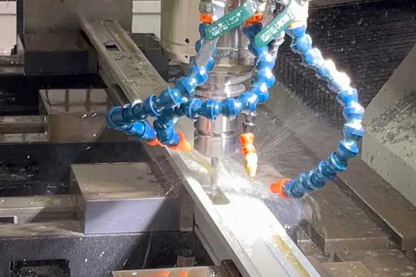
Length. Profiles are extruded in mill lengths, commonly 6 m, and the practical problems are all downstream of that number: how the lengths are shipped, how they are handled on site, and how accurately they are cut. A mill cut is typically good to about ±1 mm with a burr; a machined cut is good to about ±0.2 mm with a clean face. That difference is invisible on a 200 mm bracket and decisive on a 2,000 mm frame member, because an end that is out of square by 0.2 mm puts the far end of a 2,000 mm member 10 mm out of position. If you cannot cut square in your own workshop, buy the cut-to-length service — it is cheaper than discovering the problem at assembly.
Two questions that belong on the drawing
Which faces must be machined, and from which datum? And what evidence do you want with the delivery — a mill certificate, a dimensional report, or nothing? Both questions are free to ask before the order and expensive to raise afterwards.
The order template, in nine lines
What a supplier needs in order to quote the right thing, in the order the decisions should be taken.
- The structural inputs: unsupported span, load in kg and its position, and the deflection limit expressed either as a ratio (L/300, L/500) or as a figure in millimetres.
- The section: envelope with a reference to a drawing or a supplier code, and the wall thickness with a tolerance. “4040” alone is a category, not a section.
- The slot standard: the mouth dimension in millimetres, measured, not the series name.
- Alloy and temper: 6063-T5 for almost everything; 6061-T6 where a joint or a member is strength-limited rather than deflection-limited.
- Tolerance class: which standard governs, and the class within it. EN 755-9 indexes the tolerance to the circumscribing circle, not the side length.
- Cut length and end condition: every length, with the end condition — mill cut, machined square, tapped, or drilled to a drawing.
- Machining: hole positions, thread sizes and depths, and the datum they are measured from.
- Finish: which faces, which finish, and which faces must stay bare.
- Evidence and packing: mill certificate, dimensional report, and how the lengths have to be packed for your site.
Nine lines is more than most enquiries carry. It is also the difference between a quotation you can compare with another quotation and a price you have to take on trust.
Frequently asked questions
What is the most important thing to decide first when choosing an aluminium profile?
Does 6061-T6 give me a stiffer frame than 6063-T5?
Can I use 30 series and 40 series hardware together?
How much deflection is acceptable in an industrial frame?
What length can aluminium profiles be supplied in?
How many lines does a profile enquiry need to be comparable?
Send the span and the load, not the profile name
We extrude the 20 through 60 series and the deep beam sections in 6063-T5 and 6061-T6, cut to length, machined, tapped and finished to order. Give us the span, the load and the deflection limit and we will come back with the section and the wall that holds it, plus the cut list to match.
Related reading
Twelve more engineering notes from this blog, picked for this article — plus every category below.
 Engineering DesignT-Slot Aluminium: The Slot Mouth Is the Interface Standard, Not the Series Name
 Quality and InspectionHow to Choose (and Audit) an Aluminium Extrusion Supplier
 Sourcing and ProcurementAluminium Profile Price Breaks: How Volume Changes the Unit Price
 Sourcing and ProcurementAluminium Extrusion Price per kg in 2026 (China FOB)
 Engineering DesignCross-Brand T-Slot Compatibility: Interchangeability Is a Hardware Question
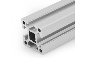 Engineering DesignWhat Is a 3030 Aluminium Profile? (Weight, Slot and Load)
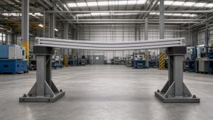 Engineering DesignAluminium Profile Max Span: Deflection Table by Section
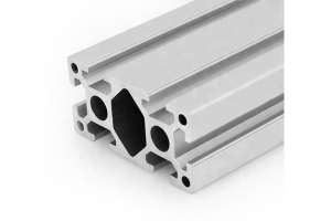 Engineering Design4080 vs 4545 Aluminium Profile: Which for Your Frame
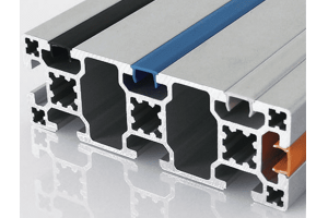 ApplicationsCleanroom and Medical Framing: There Is No Medical-Grade Aluminium Extrusion
 ApplicationsAluminium Profiles in Solar Mounting: Wind Uplift, Corrosion and a 25-Year Life
 Materials and EngineeringAnodised vs Powder Coated Aluminium Profiles: A Specification Guide for European Buyers
 ApplicationsAluminium Profiles Across Industries: What Actually Changes From One Sector to the Next
