T-Slot Aluminium: The Slot Mouth Is the Interface Standard, Not the Series Name
“40 series” is a family name, not a fit guarantee. Two suppliers can both sell a 40x40 section whose grooves will not accept the same nut. The dimension that decides compatibility is the slot mouth, and it is the one most often left off the drawing.
Short answer
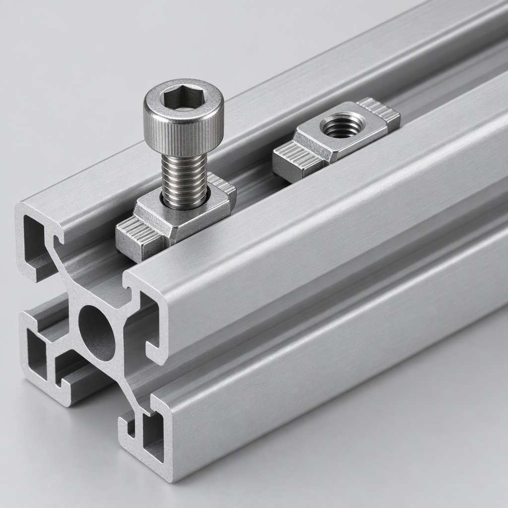
Series names such as 20, 30, 40 and 45 describe the nominal section size in millimetres, not the groove geometry. Compatibility between profile and hardware is set by two numbers: the internal groove width and the narrower mouth width at the section face. A 40 series section is typically a 10.2 mm groove with an 8 mm mouth taking M8 hardware, but that is a convention and not a standard, so the mouth width must be stated on the drawing if the hardware is to fit.
Four series, four different slot geometries
The series number is the nominal external dimension of the square section. What the hardware actually engages with is a groove whose width and mouth differ from series to series, and which changes the fastener size with it. This is why a hardware inventory built for one series cannot be assumed to transfer to another, even when the sections look broadly similar on a drawing.
| Series | Nominal section | Groove width | Slot mouth | Fastener | Slot pitch |
|---|---|---|---|---|---|
| 15 series | 15x15 up | 6 mm | 6 mm approx. | M4 | 15 mm |
| 20 series | 20x20 | 6.2 mm | 6 mm | M5 | 20 mm |
| 30 series | 30x30 | 8 mm class | 8 mm | M6 | 30 mm |
| 40 series | 40x40 | 10.2 mm | 8 mm | M8 | 30 mm |
| 45 series | 45x45 | 10.2 mm class | 10 mm | M8 | 45 mm class |
The two rows that cause the most trouble are 40 and 45. Both take M8 hardware, both are used for machine frames, and their mouth widths differ by 2 mm. A 45 series nut will not enter a 40 series groove, and a 40 series nut in a 45 series groove will sit loose enough to spin under torque. The fastener is the same; the interface is not.
Geometry, not strength
Slot geometry has a structural consequence, but that is not the point here. The point is that it is an interface standard, like a thread pitch. Two parts that both take M8 are not interchangeable for the same reason two M8 threads of different pitch are not.
Where the tolerance goes: extrusion, then anodising
The groove is formed by the die and held to an extrusion tolerance. That tolerance exists before any surface treatment, which is where the second effect comes in. Anodising is an oxide layer grown out of the aluminium, and it grows on every surface the electrolyte reaches, including the inside of the groove.
A decorative anodised layer is typically around 10 micron per face; a hard architectural or industrial layer can reach 25 micron or more. Because the layer grows outward from both groove faces, the groove loses roughly twice the layer thickness of usable width. Twenty-five micron per face removes about 50 micron from a groove, which sounds negligible until it is set against the clearance the nut was designed around.
There are two honest ways to handle this, and a supplier should be asked which one they use. The first is groove masking, which protects the slot so the as-extruded fit survives. The second is to tolerance the die so that the section measures correct after coating. A supplier who does neither is shipping a section whose hardware fit depends on how thick the batch’s anodising happened to run.
- Slot is protected during anodising
- As-extruded fit is preserved
- Adds a process step and a cost line
- Best when hardware must slide freely
- Section is extruded oversize in the groove
- Measures correct after anodising
- No extra step, but batch-sensitive
- Needs the coating thickness held tightly
Three ways a nut fails in a slot
When a T-slot joint does not hold, the nut is usually blamed and the groove is usually at fault. There are three distinct failure modes and they have three different causes, so the fix depends on which one is happening.
MODE 1
Spinning. The nut turns with the bolt instead of seating. Cause: nut is too small for the groove, or the mouth is too wide to restrain it.
MODE 2
Slip. The nut seats and then slides along the slot under load. Cause: groove face is too smooth, or the coating has filled the serrations.
MODE 3
Galling. The nut bites and then seizes before reaching torque. Cause: bare aluminium on stainless with no lubrication, or an oversize nut.
MODE 4
Lip pull-out. The mouth deforms and the nut exits the slot. Cause: wall too thin at the groove, or torque well above specification.
Each of these is a specification problem rather than a hardware quality problem. Spinning means the mouth and the nut were specified in different units of intent; slip means the finish was specified without considering friction; galling means dissimilar metals were combined without a plan; pull-out means the section’s wall thickness at the groove was never checked against the torque.
Measuring a slot you did not extrude
When a sample arrives, or when an existing frame has to be extended with hardware from a different source, the slot has to be measured rather than looked up. Three measurements are enough, and none of them needs a laboratory.
First, measure the mouth width at the face with a caliper across several points along the length; a groove that varies is a die wear problem and will produce intermittent fit. Second, measure the internal groove width by inserting the caliper’s depth-style jaws or a pair of feeler blades. Third, check the groove depth, because a shallow groove limits how much thread engagement the fastener can reach.
Then do the only test that matters: insert the actual nut and torque the actual bolt to the specified value on a short sample. If the nut spins, slip, galls or pulls out at that torque, no amount of dimensional agreement on paper changes the outcome.
Slot acceptance, in order
- Measure mouth width at three or more points along the length; variation points to die wear.
- Measure internal groove width, not just the mouth.
- Insert the real nut and torque the real bolt on a sample before unpacking the batch.
- On anodised sections, test the coated sample, not a mill-finish offcut.
- Record the supplier’s groove and mouth figures on the drawing so the next order matches.
What belongs on the drawing
A profile specification that names the series and stops there is incomplete. It will be quoted, it will be delivered, and it may not accept the hardware already on the shelf. Seven items close that gap, and every one of them is a number that a supplier can confirm before production starts.
RFQ checklist — slot geometry
State all seven. If the supplier cannot answer one of them, that is a finding in itself:
- Groove width — internal dimension, in millimetres, with tolerance.
- Mouth width — the opening at the face. This is the one usually omitted.
- Groove depth — sets how much thread engagement is available.
- Slot pitch — centre distance between slots on a face; decides bracket hole spacing.
- Wall thickness at the groove — the section that resists lip pull-out under torque.
- Surface treatment and coating thickness — state the micron class, not just “anodised”.
- Groove masking — say explicitly whether the slot is masked during treatment.
If you are matching existing hardware, send one sample nut with the enquiry and ask the supplier to confirm fit in writing. It is faster than any drawing note.
Four ways the slot gets specified wrong
Related on this site
- T-nut for aluminium profiles M4 to M10— the hardware range sized to groove and mouth
- PG40 40 x 40 four-slot heavy profile— a 10.2 mm groove with an 8 mm mouth, M8
- 40 series aluminium profiles— where the series convention is set out per section
- Extrusion tolerances: what to write and how to inspect— how to specify a tolerance you can actually check
Terms used in this article
- Groove width
- The internal width of the T-slot cavity, wider than the opening at the face.
- Mouth width
- The narrower opening at the section face through which the nut is inserted.
- Slot pitch
- Centre-to-centre distance between adjacent slots on one face; sets bracket hole spacing.
- Groove masking
- Protecting the slot interior from anodising so the as-extruded fit is preserved.
- Lip pull-out
- Failure where the groove mouth deforms and the nut exits the slot under torque.
- Galling
- Adhesive wear between two sliding metal surfaces, here between nut and groove.
Questions buyers ask
Are all 40 series profiles interchangeable?
No. The series is a nominal size family. Groove width, mouth width and slot pitch vary between suppliers, and hardware sized for one will not necessarily fit another. Treat the groove dimensions as the specification and the series name as shorthand.
Will anodising stop my nuts from fitting?
It can, if the coating is thick and the groove is not masked or compensated. A hard coat can remove tens of micron of groove width. Specify the micron class, ask whether grooves are masked, and test-fit on a coated sample.
Why does the nut spin when I tighten the bolt?
Because the mouth is not restraining it, which usually means the nut was sized for a different groove. Check the mouth width against the nut’s across-flats dimension before assuming the hardware is faulty.
Can I use stainless bolts in an aluminium slot?
Yes, but bare stainless against bare aluminium galls. Use a lubricant or a coated fastener, and be aware of galvanic corrosion if the assembly will be wet. It is a specification decision, not just a purchase.
How do I spec a section to match hardware I already own?
Send a sample nut or measure it, then specify groove width, mouth width and groove depth from the measurement rather than from the series name. Ask the supplier to confirm the fit in writing before production.
Send a sample nut, get a confirmed fit
Post or photograph the hardware you already use and we will confirm which of our sections accepts it, in writing, before you order.
Request a quoteRelated reading
Twelve more engineering notes from this blog, picked for this article — plus every category below.
 Engineering DesignAluminium Profile Anchor Pins: A Preloaded Joint, Not a Pin
 Engineering DesignPrecision Cutting and Tapping of Aluminium Profiles: The Tolerance That Actually Matters
 Applications40×40 Aluminium Profile: Where It Works, Where It Fails, and Why
 ApplicationsLean Pipe vs T-Slot Profile: Two Interface Philosophies, Not Two Generations
 Quality and InspectionAluminium Extrusion Claims: What the Contract Must Say
 Engineering DesignAluminium Profile Weight per Meter Chart (20–60 Series)
 Engineering DesignHow to Join Aluminium Profiles: Joints, Brackets and Torque
 Engineering DesignWho Owns the Extrusion Die After Tooling Is Paid?
 Sourcing and ProcurementAluminium Profile Price Breaks: How Volume Changes the Unit Price
 Machine SafetyAluminium Profile Machine Guards: Size the Frame from the Energy, Not from the Mesh
 Sourcing and ProcurementAuditing an Aluminium Profile Supplier: Factory, Trader, or Something in Between
 Sourcing and ProcurementAluminium Profile MOQ: 150 m Existing Die, 500 m New
