Quick answer
Is 40×40 the right section for your frame?
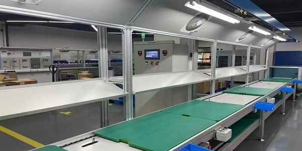
Yes for machine frames, workbenches, guarding, enclosures, conveyor side rails, control cabinets and display structures — provided unsupported spans stay under about 1,500 mm and the frame is braced against sideways load.
Only with a change where spans run past 1,500 mm, where a rail bed or fixture must hold alignment, or where the frame will be pushed sideways. Add a mid-support, brace the frame, or step up the section.
No for overhead lifting structures, long unsupported conveyor runs, or anything where a 3 mm sag is unacceptable. These are stiffness problems, and no amount of better brackets or tighter bolts solves a stiffness problem.
Why it became the default
The 40×40 module is a compatibility decision, not a strength one
40 × 40 mm won the aluminium framing market for reasons that have almost nothing to do with structural performance. It sits at the point where a slot is big enough to take a robust fastener and a panel fixing, the section is stiff enough for the spans most machines actually use, and the accessories are stocked by everyone.
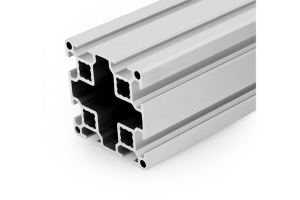
Our 4040 four-slot section is a 40 × 40 mm envelope in 6063-T5 with an M6 slot, an 8 mm slot mouth and a 30 mm slot pitch on all four faces, plus a Ø12 mm centre bore tapped M14 for through-bolting. Wall thickness is held to ±0.15 mm to EN 755-9, the same die family runs in light, standard and heavy wall from 1.30 to 2.35 kg per metre, and cut lengths are held to ±0.5 mm with machined features at ±0.2 mm.
That combination — one envelope, three walls, one slot geometry, one accessory range — is the real reason to standardise on it. A frame built entirely from one section lets you hold one bracket part number, one nut part number and one torque figure. On a production line building ten frames a month, that saves more money than any structural optimisation.
The judgement
Nine applications, and what each one actually asks of the section
The useful question is not “is 40×40 strong enough” but “what span and what load does this application produce”. Here is that translation, application by application.
| Application | Typical span | Typical load | Verdict | What decides it |
|---|---|---|---|---|
| Machine frames and bed plates | 800–1,500 mm | 50–250 kg distributed | Works | A distributed load over 1,000 mm allows about 179 kg at L/300. Add a mid-support past 1,500 mm |
| Assembly workbenches | 1,200–1,800 mm | 100–300 kg distributed | Works | Bench loads are distributed and mostly static. The 30 mm slot pitch also makes shelf and drawer repositioning easy |
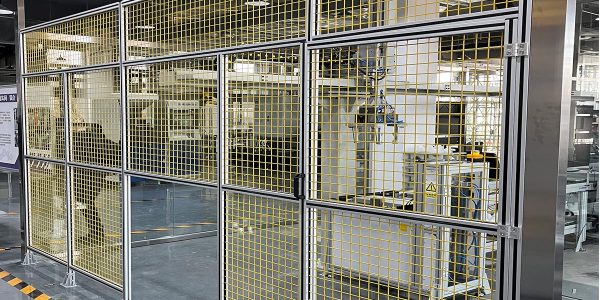
| Machine guarding | 1,000–2,000 mm | Panels, no vertical load | Brace it | The load is sideways, not down. Brackets alone rack; add a diagonal or a joining plate per plane |
| Automation and robot cell frames | 1,500–2,500 mm | Robot on a separate pedestal | Brace it | Fine as an enclosure. Do not hang the robot axis off it — dynamic loads and alignment need a heavier base |
| Conveyor side rails | 600–1,200 mm between supports | Product load plus belt tension | Support spacing | Works at 1,000 mm support spacing. Past 1,500 mm unsupported, the rail sags and the belt tracks off |
| Test rigs and measuring fixtures | Any | Any | Not usually | Needs L/500 or better. That is a stiffness requirement, met by section depth and support spacing, not by a heavier wall |
| Enclosures and control cabinets | 600–1,200 mm | Panels and door hardware | Works | Short spans, low loads. The four-slot section also lets panels mount on any face without machining |
| Display stands and exhibition frames | 1,000–2,000 mm | Very light, often lifted | Use light wall | The light wall at 1.30 kg/m is the right call here — the structure is handled far more than it is loaded |
| Overhead lifting and gantries | Any | Any | No | Lifting structures need a designed, certified section and a safety factor that aluminium framing catalogues do not provide |
The pattern in that table
Every “works” row has a span under 1,500 mm and a load that is spread out. Every “brace it” row has the load acting sideways rather than down. Every “no” row is a stiffness requirement rather than a strength one. If you remember one thing from this article: 40×40 fails because of span and sway, never because of weight.
The strength question
What “strength” actually means for a 40×40 section
Ask a supplier about the strength of a 4040 and you will usually get a load figure with no span attached. That figure is meaningless, because deflection rises with the cube of the span. The section property that governs everything is the second moment of area, I, and for a standard-wall 4040 it is about 9.8 cm⁴ — consistent with our own 45 × 45 mm section, which publishes 15.5 cm⁴, since scaling by the fourth power of the envelope gives 9.7 cm⁴ for a 40 mm square.
F = 48 × E × I × δ / L³Rearranged from the deflection formula. F is the allowable central point load in newtons, E is 70,000 N/mm² for 6063-T5, I is the second moment of area in mm⁴, δ is the allowable deflection in mm and L is the span in mm.| Section | I (cm⁴) | Weight | I per kg/m | 1,000 mm span at L/300 |
|---|---|---|---|---|
| 4040 standard | 9.8 | 1.70 kg/m | 5.8 | 112 kg |
| 4545 standard | 15.5 | 2.55 kg/m | 6.1 | 177 kg |
| 6060 heavy | 38 | 6.40 kg/m | 5.9 | 434 kg |
| 4060 on edge | 24 | 2.55 kg/m | 9.4 | 274 kg |
| 4560 on edge | 31 | 3.30 kg/m | 9.4 | 354 kg |
| 100 × 50 on edge | 150 | 6.20 kg/m | 24.2 | 1,713 kg |
Look at the fourth column, and notice the pattern in the order the rows are written. The three square sections — 4040, 4545 and 6060 heavy — all land at roughly 6 cm⁴ of stiffness per kilogram, even though their weights differ by a factor of nearly four. On a square section, going bigger adds stiffness and weight in almost exactly the same proportion.
The three rectangular sections break the pattern. Mounted on edge, the 4060 and 4560 deliver about 9.4 cm⁴ per kg/m, and the 100 × 50 delivers 24.2 — four times the square-section figure. That is the fourth-power rule at work: I rises with the cube of the section depth while weight rises roughly with its square, so depth is the only lever that genuinely improves the stiffness-per-kilogram ratio.
The consequence for buyers
If a supplier offers you a “stronger 4040” — a heavier wall at a higher price — understand what you are buying: roughly 30 to 40% more stiffness for roughly the same percentage more money per metre. That is a legitimate upgrade, but it is a straight swap rather than a bargain. If you need substantially more stiffness, the cheaper route is almost always to change the support spacing, or to step up to a rectangular section and mount it on edge.
What goes wrong
The three failure modes that actually happen in the field
The frame sags, a door stops lining up, a belt tracks off, a fixture loses its datum. Nobody notices at assembly because the sag only appears under load. This is the most common 4040 failure and the easiest to predict — run the span against the table before ordering.
An external corner bracket carries force well and moment badly. A 2,200 mm tall frame with nothing but brackets racks several millimetres when someone leans on it, which then loads the panels and cracks them at the fixings. The fix is a diagonal brace or a joining plate in at least one plane per side, not a bigger profile.
A joint tightened by feel loses preload within weeks under vibration, and the frame slowly loses square. M8 into a 40-series T-nut wants 10–15 N·m, and the ceiling is about 15 N·m because the aluminium slot lip deforms before the steel bolt does. One calibrated wrench on the first frame, then the number becomes the standard.
Worked case
An automation cell frame, 2,000 × 1,500 × 2,200 mm
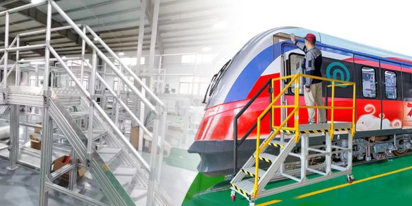
A six-axis robot on a separate pedestal, a 1,800 mm wide conveyor running through the cell, and polycarbonate panels on three sides with a sliding door on the front. The frame is 40-series throughout. Three decisions have to be made, and each one follows from the span rather than from the load.
| Element | Span | Decision | Reason |
|---|---|---|---|
| Vertical posts | 2,200 mm, no bending load | 4040 standard, four per side | Posts carry compression and are braced by the panels. Span is not a deflection problem here |
| Top rails | 2,000 mm between posts | 4040 standard plus a mid-post | At 2,000 mm unsupported a standard 4040 carries about 28 kg centrally at L/300. The mid-post removes the question entirely |
| Conveyor support beams | 1,800 mm | 4080 on edge, or 4040 with two supports | Belt tracking needs alignment, so this joint needs L/500 or better. Depth is the cheaper route than a heavier 4040 |
| Panel mounting | — | Four-slot section | Panels need fixings on three faces plus the frame joints. A three-slot section would force panel blocks onto the same faces as the connectors |
| Sway control | — | One diagonal brace per long side | The frame is 2,200 mm tall with bracket-only joints. Without bracing it racks before the panels are fitted and loads them afterwards |
| Robot base | — | Not on the 4040 frame | Dynamic loads, alignment and safety all point to a separate steel or heavy-section pedestal, isolated from the enclosure frame |
The interesting thing about that table is how little it depends on load. Every decision came from span, alignment requirement or load direction. That is characteristic of aluminium framing: the strength is almost always there, and the stiffness and the bracing are what you are really designing.
For the accessories, the profile range is on the 40 series aluminium profiles page, and the section itself is 4040 4-slot strut profile. If you need a deeper section for a rail bed, the 4060 is the next step up in the same family, and the 45 series covers the heavier automation frames.
Frequently asked questions
What is a 40×40 aluminium profile used for?
Machine frames, workbenches, machine guarding, automation and robot cell enclosures, conveyor side rails, control cabinets and display structures. It is the default section in aluminium framing because the slot is large enough for a robust fastener, the section is stiff enough for the spans most machines use, and the accessory range is universally stocked.
Is 40×40 aluminium profile strong enough for a machine frame?
For strength, yes — aluminium framing fails by deflection, not by yielding. For stiffness, it depends on span. Under about 1,500 mm with distributed loads, a standard 4040 is comfortable. Past that, add a mid-support or step up to a deeper section. The strength of the material is almost never the limiting factor.
Is a heavier wall worth the extra cost?
It is a fair trade but not a bargain. On a square section, a heavier wall raises the second moment of area by roughly the same percentage as it raises the weight and the price — around 30 to 40%. If you need substantially more stiffness, a rectangular section mounted on edge delivers far more per kilogram, because stiffness rises with the cube of the section depth while weight rises with the square.
What is the difference between a square and a rectangular profile?
Stiffness per kilogram. Square sections — 4040, 4545, 6060 — all deliver roughly 6 cm⁴ of stiffness per kg/m, because going bigger adds stiffness and weight in nearly the same proportion. Rectangular sections mounted on edge deliver much more: our 40 × 60 reaches about 9.4 cm⁴ per kg/m and the 100 × 50 reaches 24.2. The catch is orientation, which has to be marked on the cut list because a rectangular section mounted flat loses up to half its advantage.
Can 40×40 profiles be used for automation equipment?
Yes for the enclosure, guarding and support structure, which is where most of the section is used. No for a robot or gantry base, where dynamic loads and alignment requirements call for a heavier designed section, usually isolated from the enclosure frame. Mixing the two roles on one frame is a common and expensive mistake.
How do I stop a 40×40 frame from swaying?
Add bracing. External corner brackets behave close to pin-jointed, so a tall frame with bracket-only joints racks under a sideways push. One diagonal brace or joining plate in at least one plane per side is normally enough. A heavier profile does not fix sway efficiently, because the problem is joint stiffness rather than member stiffness.
Tell us the application and we will tell you the section
Describe the frame, the spans and what it carries. We will come back with the wall variant, the support spacing and the bracing, in 6063-T5 to EN 755-9.
Related reading
Twelve more engineering notes from this blog, picked for this article — plus every category below.
 Engineering DesignAluminum Corner Brackets for T-Slot Frames: How to Choose by Load Path, Not by Looks
 Engineering DesignAluminum vs Steel Machine Frames: Choose by Deflection, Not by Strength
 Engineering DesignAluminium Profile Weight per Meter Chart (20–60 Series)
 ApplicationsAluminium Profile Display Boards: The Panel Is the Hard Part
 Engineering Design6063 vs 6061 vs 6082 and T5 vs T6: What Changes in Practice
 Engineering Design30 Series T-Slot Profiles: The Middle That Has to Justify Itself
 Engineering Design3030 vs 4040 Aluminium Profile: Which for Your Frame
 Engineering DesignAluminium Profile Anchor Pins: A Preloaded Joint, Not a Pin
 Sourcing and ProcurementFOB vs CIF vs DAP vs DDP: Aluminium Profile Landed Cost
 Sourcing and ProcurementPayment Terms for Aluminium Profile Orders (T/T, L/C and the Risk)
 Materials and EngineeringAnodised vs Powder Coated Aluminium Profiles: A Specification Guide for European Buyers
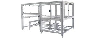 Machine SafetyAluminium Profile Machine Guards: Size the Frame from the Energy, Not from the Mesh
